


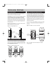

14
CA6.4
•Frequency Response: 20 Hz to 20 KHz ( +/- 1 dB )
•20 Watts RMS / Channel @ 8Ω
•12 Channels / 6 Stereo Amplifiers
•Total Harmonic Distortion: .01%
•Signal to Noise Ratio: 89 dB min, “A” weighted
•Power Supply: 110/220V High Current Torroidal
•ETL listed. Conforms to UL Standard UL1492 and CSA
Standard C22-2 No. 1-M94
•Fully Functional Keypad with IR Receiver Centered at
40 kHz and 56K kHz
CA4.4pi
•Frequency Response: 20 Hz to 20 KHz ( +/- 1 dB )
•20 Watts RMS / Channel @ 8Ω
•8 Channels / 4 Stereo Amplifiers
•Total Harmonic Distortion: .01%
•Signal to Noise Ratio: 89 dB min, “A” weighted
•Power Supply: 110/220V High Current Torroidal
•ETL listed. Conforms to UL Standard UL1492 and CSA
Standard C22-2 No. 1-M94
•Fully Functional Keypad with IR Receiver Centered at
40 kHz and 56K kHz
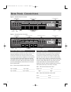
SPECIFICATIONS
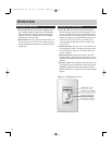
TROUBLESHOOTING
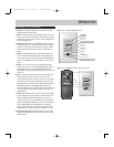
KEYPAD WIRING PROTECTION CIRCUIT
To provide protection for incorrect keypad wiring, this CA-
Series product is equipped with a short circuit protection
device. In the event of a keypad cable short, or incorrect
keypad wiring, this device will automatically interrupt power
to all keypad ports.
Once installed, if the keypads connected to your CA-Series
product will not turn on, the short circuit protection device
may have been activated. Please take the following steps to
troubleshoot the system.
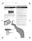
1)Turn off the power switch on the front of the CA-Series
controller.
2)Disconnect all keypad connections from the rear of the
controller.
3)Check the wiring configuration for each keypad, checking
both ends (the CA unit and the CA keypads) of the CAT-5
keypad cable.
4)If incorrect connections were found, correct the wiring
and reconnect the keypads to the controller. After the
controller has been powered off for at least 15 seconds,
turn on the power switch of the CA-Series controller.
5)If the problem persists, repeat steps above trying each
keypad consecutively.
6)Inadequate ventilation can allow normal heat to build up
and trip the protection circuit.
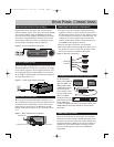
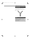
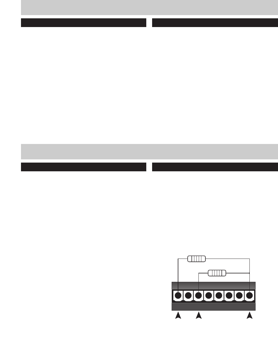
ELIMINATION OF BALANCE LINE
The following diagram shows how resistors may be used at
the Keypad connection on the rear of the CA master control
unit, to provide 2.5VDC to the balance control line for cen-
tering. This circuit will stabilize the balance line input and
keep it centered. They can be used to free up one of the 8
required conductors if one is open, shorted or if an extra
conductor is needed for a secondary IR receiver’s signal in
that zone. Position #1 is GND, #3 is 12VDC, #8 is Balance.
CA Keypad Connector @ Rear of Processo
r
GND
+12VDC
Balance
820 Ohm 1/4w
3.9K Ohm 1/4w
12345678
CA-Series manual R6 10/17/01 1:50 PM Page 14