


SURROUND SOUND PROCESSOR RSP-985
16
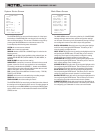
External In Jack
25
This 3.5 mm jack accepts a remote infrared sensor which dupli-
cates the function of the front panel IR sensor in installations
where the front panel sensor could be blocked by a cabinet. See
your authorized Rotel dealer for a selection of remote sensors that
will work with your RSP-985.
Rear Panel Output Connections
This section of the manual provides complete information on all of
the audio and video signal output connections on the rear panel of
the RSP-985. For convenience, each topic begins with an over-
view of the particular connection, followed by detailed hookup in-
structions.
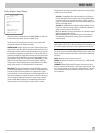
RCA Audio and Video Outputs
13
[See Figure 4]
These three sets of RCA outputs (VIDEO 2, VIDEO 3, and VIDEO 4)
include left and right channel audio plus composite video outputs
from the RSP-985 to appropriate components (VCR, etc.) for re-
cording or further processing. Standard color coding applies.
Connect the RSP-985's VIDEO 2 left and right audio outputs to the
audio inputs of the first source component. Then, connect the
VIDEO 2 composite video output to the video input of the same
source component. Repeat these steps for VIDEO 3 and VIDEO 4
connections.
To avoid mistakes, make sure that you:
• Connect the source component’s outputs to the appropriate
RSP-985 inputs
• Connect the appropriate RSP-985 outputs to the source compo-
nent inputs.
• Make sure that whatever video component is connected to the
VIDEO 2 inputs is the same component connected to the VIDEO 2
outputs, etc.
Note 1: The signal available at these outputs is determined by the
RECORDING input selection buttons and is not necessarily the
same source as that selected by the LISTENING input selection
buttons.
Note 2: A source’s signal cannot be sent back to itself. For ex-
ample, if you select VIDEO 2 with the RECORDING select buttons,
the outputs for VIDEO 2 will be muted and you can only record
from the VIDEO 3 or VIDEO 4 outputs.
Note 3: Only analog input signals are routed to the VIDEO OUT
jacks. If you are using a digital input, you should also connect the
analog output of the source component for recording.
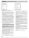
S-Video Outputs
24
[See Figure 5]
Mini-DIN outputs give you the option of using S-Video outputs in-
stead of the RCA composite video connections described above.
Note: Composite video signals cannot be converted to S-Video
signals. There will be no signal available at the S-Video outputs
unless S-Video connections have also been used at the inputs.
If you have opted for S-Video connections rather than composite
RCA video connections, connect the S-Video outputs for VIDEO 2
to the S-Video input on your first source component.
Remember that you are merely substituting an S-Video connection
for the standard RCA-style composite video connection. Your au-
dio connections will still use the RCA outputs described above.
Also remember to observe the same component-to-component
continuity between audio and video signals described above.
Repeat the same process using VIDEO 3 and VIDEO 4 if you have
additional video source components.
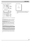
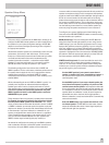
Main Processor RCA Audio Outputs
18
[See Figure 3]
The RSP-985 sends six channels of audio to the power amplifiers.
These outputs (6 individual RCA-style jacks) direct the RSP-985’s
main output to power amplifiers for speakers in the primary listen-
ing/viewing area. These six outputs (Left Front, Center Front, Right
Front, Left Surround, Right Surround, and Subwoofer) connect the
RSP-985's main audio output to a multichannel power amplifier or
multiple power amplifiers for the primary listening area.
Standard color coding applies with black insets to distinguish
Center Channel and Subwoofer outputs from Left (white) and Right
(red) Front and Rear outputs. To hook up the RCA main audio out-
puts, connect a standard audio cable from each output to the in-
put of the amplifier channel that will power the corresponding
speaker. In a full home theater system, you will need to make six
different connections corresponding to the six speakers (Left
Front, Center Front, Right Front, Left Surround, Right Surround,
and Subwoofer).
It is important to make sure that you have the correct output con-
nected to the proper amplifier channel. Take your time and you
will have no trouble getting it right.
Main Processor 25-pin Audio Outputs
17
[See Figure 3]
As an alternative to the RCA outputs , the RSP-985 also provides
DB25 multi-pin output connector which carries all output channels
in a single cable. The DB25 output connector provides exactly the
same signal as the RCA outputs, but is more convenient for use
with Rotel, or other, multichannel amplifiers equipped with a
matching DB25 input. Choose whichever is most convenient for
your system hookup.
To use the DB25 output connections, simply connect a female-to-
male DB25 audio cable from the output of the RSP-985 to the
matching input on the multichannel power amplifier.