


RSP-985
11
The RSP-985 can generate heat during normal operation. Do not
block ventilation openings. Allow a minimum of 10 cm (4 inches) of
unobstructed open space around the unit. If installed in a cabinet,
make sure that there is adequate ventilation.
Make sure there is enough room behind the RSP-985 for easy
hookup. Remember, you are connecting many other components
to this unit and you’ll probably need more space than you think.
Don’t stack other objects (components or other items) on top of
the RSP-966. Don’t let water fall into the RSP-966 as this could
damage delicate circuitry.
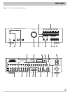
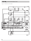
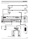
Front Panel Controls
Although we have designed the RSP-985 to be as simple to use as
possible, it is still a complex piece of equipment. For that reason,
we suggest you look over the RSP-985’s front and rear panels be-
fore you start connecting other components to it. The following
brief explanations provide an overview of the unit’s connections,
features, and controls, with number references corresponding to
the illustrations at the front of this manual.
Most functions are duplicated on the front panel and on the
handheld remote control, a few only on one or the other. These
duplications are noted below. In addition, when two reference
numbers appear, one refers to the location of the button on the
front panel, the other to the location of the button on the handheld
remote control.
Standby LED
3
Some of the RSP-985’s circuitry (microprocessor, infrared sensor,
etc.) remains powered at all times, while the rest of the circuitry is
turned on or off by the user. The STANDBY LED lights whenever
the RSP-985 is plugged into a live AC outlet but does not neces-
sarily mean that the RSP-985 is totally active. If other front panel
LEDs are lit, then the RSP-985 is fully functional.
Note: During system setup, it is possible to select an alternative
FULLY-ON power-up mode in which the unit is fully activated
whenever it is connected to a live AC outlet.
Standby Switch
2
Similar to a power switch in function, this button switches the
RSP-985 from standby mode to fully active mode. If only the
STANDBY LED is lit, push the front panel (or handheld remote
POWER button) to fully activate the RSP-985. Other front panel
LEDs light up and a welcome screen will appear on your TV set.
Push the STANDBY switch again to deactivate the RSP-985. You'll
see that only the STANDBY LED remains lit.
Note: The STANDBY switch also controls the rear panel AC power
outlets. When the RSP-985 is in
STANDBY
mode, the AC outlets
are off. When the RSP-985 is functional, the AC outlets are live.
The operation of the STANDBY switch is somewhat more elabo-
rate when using the RSP-985’s ZONE 2 capability. For a detailed
explanation, see the ZONE 2 Connections and Operations section
of this manual.
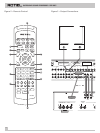
Remote Sensor
1
This sensor receives infrared signals from the handheld remote
control. Make sure you do not accidentally block this sensor with
cables or accessories.
Master Volume Control
4
Turn this control clockwise to raise and counterclockwise to
lower the volume to all six main output channels simultaneously.
MASTER VOLUME buttons are also available on the RSP-985's
handheld remote control.
Note: The MASTER VOLUME control is mechanically connected to
an internal servomotor and responds to commands from the
handheld remote. It will rotate in the appropriate direction auto-
matically when adjusting the volume from the remote control.
Use the position of the LED indicator on the knob’s outer edge to
determine relative volume settings. When the volume control LED
blinks, you’ve engaged MUTE from the remote controller.
Tone Controls
6
BASS and TREBLE controls increase and decrease the audio
signal’s low and high frequency content. Rotate each one clock-
wise to increase output in the respective frequency range and
counterclockwise to reduce it. The center detent removes each
control from the audio path for maximum signal integrity. The ON-
SCREEN DISPLAY will show tone control settings as you adjust
them.
Note: The BASS and TREBLE controls are bypassed in THX mode
and will have no effect, regardless of the setting indicated by the
ON-SCREEN DISPLAY.
Listening Input Source Buttons
11
Six front panel pushbuttons select an audio/video input source
such as a CD player, VCR, Laser Disc Player, etc. Push any of
these buttons (or the duplicates on the handheld remote) to select
the desired source. You will hear this source and, if you have se-
lected a video source, see its picture on your TV. An LED indicator
on each pushbutton lights to confirm your selection. In addition,
the ON-SCREEN DISPLAY confirms your selection.
Note: The source inputs can accommodate either analog signals
or digital signals. This selection is made from the ON-SCREEN
MENU system during initial setup of the system.