


7
Auxiliary Power Outputs
(U.S.A. version)
The RA-972 has a switched outlet on the back
panel. Power is available from this outlet when
the RA-972 is turned on. The outlet can pro-
vide up to 400 watts. It is appropriate for sup-
plying power to a signal source, such as a
CD player, tuner, or tape deck. It should not
be used for power amplifiers. Connecting a
component that will draw more than 400 watts
from this output could damage the Power
Standby switch in the RA-972.
12 Volt Trigger Outlet
Some audio components can be turned on
automatically when they receive a 12V turn
on “signal”. The 12V Trigger Output of RA-972
provides the required signal. Connect the com-
patible components to the RA-972 with a
conventional 1/8” miniplug cable.
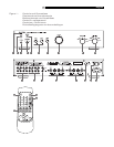
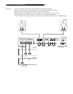
Input Signal Connections
[See Figure 2 for input connection il-
lustration.]
The RA-972 has conventional RCA type in-
put connectors, the type found on nearly all
audio equipment.
Note: To prevent loud noises that neither
you nor your speakers will appreciate,
make sure the system is turned off when
you make any signal connections.
All the inputs of the RA-972 are “line level’
inputs. These are appropriate for connecting
components such as CD players, Hi Fi or
NICAM Stereo video cassette recorders, tuners
for audio or video, Laser Disc players or the
analog output from a CD ROM drive. If you
want to use a phonograph with the RA-972,
an external phono equalizer, such as the Rotel
RQ-970BX must be used.
The Left and Right channels are clearly labeled
and should be connected to the correspond-
ing channels of the source component. The
Left RCA connectors are white, the Right con-
nectors are red. Use high quality RCA cables
for connecting input source components to the
RA-972 . Ask your authorized Rotel dealer
for advice about cables.
Recorder Connections
[See Figure 2 for recorder connection
illustration.]
The Tape 1 and Tape 2 inputs and outputs can
be connected to any record/playback device
that accepts standard line level analog input
and output signals. Typically that will be a con-
ventional tape recorder.
When connecting a recorder to the RA-972
remember that the outputs of the recorder must
be connected to the tape inputs of the RA-972.
Similarly the tape outputs of the RA-972 must
be connected to the inputs of the recorder. As
with other sources be sure to connect the Left
and Right channels of each device to the proper
channels on the associated components. Use
high quality connecting cables to prevent loss
of sound quality.
Preamp Outputs
The RA-972 has a set of preamp outputs. The
signal from the source selected with the Lis-
tening Selector is always available from these
outputs. Typically these outputs are used to
provide a signal to another integrated am-
plifier or power amplifier, which is used to drive
remote speakers
Speaker Outputs
Speaker Selector Switch
[See Figure 2 for speaker connec-
tion illustration.]
The RA-972 has two sets of speaker outputs,
labeled “A”
and “B” . The speaker out-
puts are controlled by the switch
on the
front panel.
Speaker Selection
If only one set of speakers will be used at any
given time, the speakers may have an imped-
ance as low as 4 ohms. If there are times when
both the A and B speakers will be used, all
the speakers should have an impedance of
8 ohms or more. Speaker impedance ratings
are less than precise. In practice, very few loud-
speakers will present any problems for the
RA-972. See your authorized Rotel dealer if
you have any questions.
Speaker Wire Selection
Use insulated two-conductor stranded wire to
connect the RA-972 to the speakers. The size
and quality of the wire can have an audible
effect on the performance of the system. Stan-
dard speaker wire will work, but can result
in lower output or diminished bass response,
particularly over longer distances. In general,
heavier wire will improve the sound. For best
performance, you may want to consider spe-
cial high-quality speaker cables. Your autho-
rized Rotel dealer can help in the selection
of cables for your system.
Polarity and Phasing
The polarity – the positive/negative orienta-
tion of the connections – for every speaker
and amplifier connection must be consistent
so all the speakers will be in phase. If the po-
larity of one connection is reversed, bass output
will be very weak and stereo imaging de-
graded. All wire is marked so you can iden-
tify the two conductors. There may be ribs or
a stripe on the insulation of one conductor.
The wire may have clear insulation with dif-
ferent color conductors (copper and silver).
There may be polarity indications printed on
the insulation. Identify the positive and negative
conductors and be consistent with every
speaker and amplifier connection.
Speaker Connection
Turn off all the components in the system be-
fore connecting the speakers. The RA-972 has
color-coded binding post type speaker connec-
tors on the back panel (except in European Com-
munity countries where their use is not permit-
ted). These connectors accept bare wire, con-
nector lugs, or dual banana type connectors.
English