


7
English
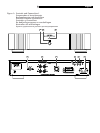
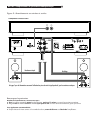
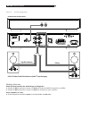
Speaker Connection
See Figure 2
The RB-1091 has two sets of dual binding post
speaker connection terminals. In addition there
is a four-contact Speakon
®
connector. Some
speakers also have Speakon
®
connectors
which make it easy to connect the speakers by
simply plugging in wires that are terminated
with Speakon
®
plugs. Even if your speakers
do not have Speakon
®
connectors you can still
use speaker wires that have Speakon
®
plugs
on one end.
Speaker Selection
The nominal impedance of the loudspeaker(s)
connected to the RB-1091 should be no lower
than 4 ohms.
Speaker Wire Selection
Use insulated two-conductor stranded wire to
connect the RB-1091 to the speakers. The size
and quality of the wire can have an audible ef
-
fect on the performance of the system. Standard
speaker wire will work, but can result in lower
output or diminished bass response, particularly
over longer distances. In general, heavier wire
will improve the sound. For best performance,
you may want to consider special high-quality
speaker cables. Your authorized Rotel dealer
can help in the selection of appropriate cables
for your system.
Polarity and Phasing
The polarity – the positive/negative orientation
of the connections – for every speaker and
amplifier connection must be consistent so all
the speakers will be in phase. If the polarity
of one connection is mistakenly reversed, bass
output will be very weak and stereo imaging
degraded. All wire is marked so you can
identify the two conductors. There may be ribs
or a stripe on the insulation of one conductor.
The wire may have clear insulation with dif
-
ferent color conductors (copper and silver).
There may be polarity indications printed on
the insulation. Identify the positive and nega
-
tive conductors and be consistent with every
speaker and amplifier connection.
If you are using Speakon
®
plugs be sure the
wires are connected to the proper terminals
on the plug.
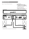
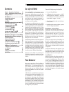
Conventional Speaker Wire
Connections
5
The RB-1091 has two sets of color coded
terminals. Having two sets of terminals makes
it easy to biwire a speaker. The speaker
terminals accept bare wire, connector lugs,
or “banana” type connectors (except in the
European Community countries where their
use is not permitted).
Route the wire(s) from the RB-1091 to the
speakers. Give yourself enough slack so you
can move the components to allow access to
the speaker connectors.
If you are using banana plugs, connect them
to the wires and then plug into the backs of the
speaker connectors. When using banana plugs,
the collars of the binding post terminals should
be screwed in all the way (clockwise).
If you are using terminal lugs, connect them
to the wires. If you are attaching bare wires
directly to the speaker connectors, separate the
wire conductors and strip back the insulation
from the end of each conductor. Be careful
not to cut into the wire strands. Unscrew (turn
counterclockwise) the binding post collar. Place
the connector lug around the shaft, or insert
the bundled wire into the hole in the shaft. Turn
the collars clockwise to clamp the connector
lug or wire firmly in place.
NOTE: Be sure there are no loose wire
strands that could touch adjacent wires or
connectors.
Speakon
®
Speaker
Connection
6
The RB-1091 has a four-contact Speakon
®
speaker connector. The four contact connectors
make it easy to make biwire speaker connec
-
tions. The connector on the RB-1091 also ac
-
cepts two contact Speakon
®
connectors if you
do not plan to biwire the speakers.
Pre-wired Speakon
®
connector cables are
available. You may also wire your own cables
using wire you choose.
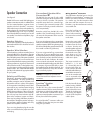
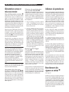
Wiring Speakon
®
Connectors
This information describes how to wire the
NL4FC four-contact Speakon
®
connector. The
NL2FC two-contact connector is connected
in a similar way. See the instruction sheet
that comes with the connector for more in
-
formation, or go the manufacturer’s web site,
www.neutrik.com.
Place the bushing and
chuck on the cable as
shown before attaching
the wires to the terminals
on the insert.
Remove the outer jacket
of the wire and strip the
insulation from the wires
as shown. Twist the wire
strands together and insert
it into the terminal. Tighten
the terminal screw with a
screw driver or a 1/16”
allen wrench to clamp the
cable wire in place.
The insert terminals are
labeled 1+, 1–, 2+ and
2–. Connect the wires to
the terminals of the con
-
nector insert for the other
end of the cable before you
assemble the connectors so
you can be sure that each
wire is connected to the
corresponding terminal on
each insert.
Push the insert all the way
into the housing. Slide the
chuck down the wire into
place behind the insert.
Thread the bushing onto
the housing and tighten
it so the chuck clamps the
cable in place.