


– 3 –
Design Features
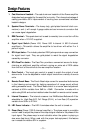
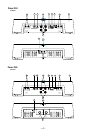
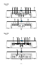
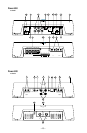
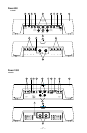
1. Cast Aluminum Heatsink – The cast aluminum heatsink of the Power amplifier
dissipates heat generated by the amplifier's circuitry. The inherent advantage of
casting provides a 30% improvement of cooling over conventional extrusion
heatsink designs.
2. Speaker/Power Terminals – The heavy duty, gold-plated terminal block con-
nectors (+ and –) will accept 4 gauge cable and are immune to corrosion that
can cause signal degradation.
3. REM Terminal – This spade terminal is used to remotely turn on and turn off the
amplifier when +12V DC is applied.
4. Signal Input Switch (Power 400, Power 800 4-channel & 600 5–channel
amplifiers)
– This switch allows the amplifier to be driven with either 2 or 4
pairs of inputs.
5. RCA Input Jacks – The industry standard RCA jacks provide an easy connection
for signal level input. They are gold-plated to resist the signal degradation
caused by corrosion.
6. RCA Pass-Thru Jacks – The Pass-Thru provides a convenient source for daisy-
chaining an additional amplifier without running an extra set of RCA cables
from the front of the vehicle to the rear amplifier location.
7. Gain Control – The input gain control is preset to match the output of most
source units. It can be adjusted to match output levels from a variety of source
units.
8. Remote Punch Bass – The Punch Bass helps correct for acoustical deficiencies
in the listening environment by helping reproduce full range sound without
adding excessive boost. The Punch Bass control is a narrow band adjustment
centered at 45Hz variable from 0dB to +18dB. Connection is made with a
cable using RJ-45 and can be installed under the dash for remote control access.
9. Internal Crossover – The internal crossover is a 24dB/octave Butterworth filter
selectable for High-Pass (HP), Full Range (FULL), or Low-Pass (LP) operation
variable from 50Hz to 210Hz.
10. LED Power Indicator – The LED illuminates when the unit is turned on.
11. Phase Warp (Power 1000 2-channel amplifier) – The phase warp is a variable
control used to adjust the phase of the output signal relative to the phase of the
input signal. The phase warp is most noticable when the system is playing a
sine wave (test tone). When used with the proper test equipment, this feature
can increase the relative SPL in a system.