


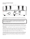
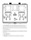
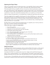

34 – 37. Output Tube Sockets V1 – V4 The four EL-34/6CA7 output tubes supplied with the
amplifier fit the Output Tube Sockets. The base of each tube is marked with the socket number
where that tube was used when the amplifier was aligned at the factory. For best performance, each
tube should be used in the corresponding socket. The front of each tube socket has a red LED indica-
tor that lights when the fuse for that socket has blown, or the fuse is not in its socket.
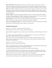
38. Mounting holes for Transformer Cover or optional full Cage Cover. The optional full Cage
Cover replaces the standard Transformer Cover. To mount the cage, push gently on both sides and
insert the mounting pins into the four holes. To remove the cage, lift both sides making sure that you
clear the tubes and transformers. *The full cage is optional and will replace the transformer cover
when it is in use.
Installing Your Model 5 Amplifier
Please follow this installation procedure when you place the amplifier into service. The time you
invest in proper installation and bias alignment will reward you with many hours of fine perfor-
mance.
1. Confirm that the Power switch is set to OFF. Don’t try to install the amplifier with the Power
switch in the STBY or ON position.
2. Confirm that the AC power cord is not connected to the amplifier. Place both ground
switches in the GROUND position
3. Consult the specifications for your speaker to find their nominal impedance.
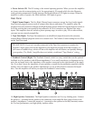
4. Use a small flat-blade screwdriver to move the red marks on the right and left Feedback
Controls to the correct impedance setting for your speakers.
5. Set the output tube operation switch to ultralinear. After installtion you may want to experi-
ment with both settings to choose the one that sounds better with your speakers and program
sources.
6. Place the amplifier in the location where it will operate.
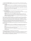
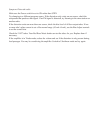
7. Connect the speaker cables between the amplifier and your speak-
ers. The Model 5 is a non-inverting amplifier, so the speaker
cables should be connected with absolute polarity. Positive (+)
from the Model 5’s amplifier output binding post to the positive
(+) speaker binding post and negative (0Ω) to the negative (–)
speaker binding post.
Note: For best performance, always use the output impedance
closest to the speaker manufacturer’s impedance rating, i.e. 4 ohms to 4 ohms. Be
careful to only connect the speaker wiring between the negative lead (0 Ω) and a single
(+) 6Ω positive output impedance (as one example). Avoid connecting the speaker cable
connectors between the (+) 6Ω and (+) 8Ω taps or the (+) 6Ω and the (+) 4Ω which will
cause the amplifier to malfunction.
For best performance, use quality speaker cables.
May we suggest you use our Red Rose Music cables as a good system match.
8. Place Transformer cover after installing the four retaining pins through the threaded inserts
located on the bottom. The (optional) Full Cage Cover is shipped separately.
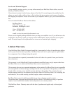
9. Aligning the pins to the pattern in sockets (Note: The space in the tube and socket), Insert
the four 12AT7 tubes into their sockets. When they are firmly seated, wipe each tube with a
clean soft cotton cloth to remove fingerprints and oils transferred from your fingers, which
can reduce the life of the tubes. Please locate the cotton gloves to minimze contact with the
tube’s glass envelope.