


RRW1A • 6
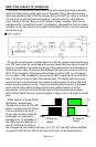
When the IR detector on the RRW1A (transmitter board) “sees” a 38 kHz IR
signal, the output of the detector goes low (it is inverted). When there is no 38
kHz signal present the output idles high. On the output of the IR detector you
won’t see the 38 kHz, just the data that the 38 kHz represents from your IR
remote control. This data from the IR detector is then used to switch on and
off a 433.42 MHz oscillator. Instead of switching an LED on and off at 38 kHz,
we are now switching an electrical field on and off at a rate of 433.42 MHz.
This acts as our new carrier frequency for the wireless part of the kit.
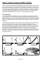
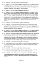
The oscillator section is a Colpitts style oscillator formed by Q2, C7, C8, R6,
and X1. The oscillator is turned on and off by Q3 through resistor R4 in accor-
dance with the received IR data. When a data pulse is detected by U1, its out-
put goes low pulling the base of Q3 low to turn it off. When Q3 turns off, the
collector (R3, R4, and Q3 junction) is pulled high so the needed bias voltage is
applied to R4 causing Q2 to turned on and begin oscillating with the surround-
ing parts. Turning Q2 on and off performs the on-off data keying (OOK modu-
lation) that we require to re-broadcast the IR signal.
The RRW1B (receiver board) has a specialized receiver chip which is also
set at 433.42 MHz. The receiver detects whether or not a 433.42 MHz field is
being broadcast and only sets its data output high if a signal is present. The
RRW1B will replicate the transmitted data by turning its data out pin on and off
at the received data rate. To re-send this data, we have to modulate a 38 kHz
carrier again in accordance with the data the IR detector puts out. By using a
micro-controller the data output from the IR detector can be sampled and a
Pulse Width Modulated (PWM) signal at 38 KHz can be generated in accor-
dance with the detected data.
By using this method with a micro-controller, we can add some intelligence
to the regenerated signal as well. The sample IR remotes we have looked at
send their data at a rate of around 2400 bits per second. This means that our
minimum pulse length for a zero should be 1/2400 x 0.30 seconds long (125
uS). Consider this example, let’s say that the signal from the IR remote is
weak and it fades out due to interference from some other IR source before
the data pulse is finished (i.e. 80 uS instead of 125 uS). The micro-controller
will continue to send the 38 kHz until 125 uS is up, not allowing the re-
transmitted signal to drop out the way the original source did. This error cor-
rection feature can be disabled in case you have a strange remote that is not
compatible (to this point we have yet to run across one that doesn’t work). Re-
move the jumper from J21 to disable this feature and have U21 blindly re-
create the data it sees.
Once the micro-controller on the receiver board has re-generated the 38 kHz
carrier (modulated by the data), its output is buffered by a transistor stage that
drives the high power IR LED used to control your equipment.
Wow! There’s a lot going on here!