


RRW1A • 11
10. Install R4, a 22K ohm resistor (red-red-orange).
11. Install C4, a 47 pF ceramic capacitor (marked 47). This capacitor works
with Q1 to isolate the antenna from the oscillator section. The capacitor
value of 47 pF was chosen because it looks like a direct short to ground at
433 MHz so any RF on the base of Q1 is removed!
12. Install C1, a 47 pF ceramic capacitor (marked 47).
13. Install C2, a 0.01 uF ceramic capacitor (marked .01 or 103 or 10 nF).
Both C1 and C2 are used as power bypass capacitors to keep RF signals
out of the power supply. While a 47 pF capacitor looks like a short at 433
MHz, a 0.01 uF ceramic capacitor does not. Why do we use a 47 pF right
next to this 0.01 uF ceramic capacitor? This bypasses the 433 MHz and
any other low frequency signal that could be present. It is a good practice to
bypass RF stages in this manner to remove any possible noise in the
system.
14. Install R1, a 470 ohm resistor (yellow-violet-brown).
15. Install R2, a 2.2K ohm resistor (red-red-red). R1 and R2 form a bias
network for Q1, which allows a certain amount of current to be available to
Q2 when oscillation begins. They also work in conjunction with C4 above to
isolate the oscillator from the antenna.
16. Install C6, a 47 pF ceramic capacitor (marked 47). This capacitor helps
to keep any 433 MHz signal from feeding back on our data input circuit.
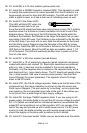
17. Install Q3, a 2N3904 NPN transistor (marked 2N3904). Pay attention to
the flat side for orientation. This transistor is needed to invert the data
output of the IR detector. If you remember from the circuit description, the
output of the IR detector goes low when a signal is detected. We want to
transmit a signal whenever that output goes low so we need to invert the
low to a high to turn the oscillator stage on when the IR signal is seen.
18. Install R3, a 4.7K ohm resistor (yellow-violet-red).
19. Install JMP1 using a spare piece of component lead. Since this layout is
on a single sided board, some routes just couldn’t be performed without
adding this jumper.
20. Install R5, a 10K ohm resistor (brown-black-orange).
21. Install U1, the IR detector. Pay attention to the orientation and make
sure all leads are through the holes before soldering in place.
22. Install C5, a 0.1 uF ceramic capacitor (marked .1 or 104 or 100 nF).
This bypass capacitor reduces any noise on the power supply line just
before going into U1. We don’t want any noise here to give us false data
pulses!