


RRW1A • 10
ASSEMBLY OF THE RRW1A
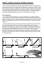
Assembly of the RRW1A is straight forward but it does require some time
and patience. To get our bearings, we will start by mounting the power jack
and move on from there. It serves as a good reference point for the other
parts.
1. Install J1, the 2.1 mm power jack. Be sure to get a solid connection to
all three pads as this will have to take some mechanical strain during
normal use. Use ample solder (without ‘globbing’ it on of course).
2. Install R6, the 270 ohm resistor (red-violet-brown).
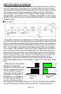
3. Install C7, the 2.2 pF ceramic capacitor (marked 2.2). C7 acts as the
feedback path for our “Colpitts” style oscillator. This capacitor combined
with the next one (C8) and the saw resonator (X1) make this circuit
oscillate at the required frequency. Note that this is one of the rare
exceptions to installing at 90 degree angles. This part is actually installed
at a 45 degree angle to keep lead lengths as sort as possible. This goes
to show how important it is to keep your lead lengths short! Even a small
amount of trace can introduce inductance that may prevent our oscillator
from working properly.
4. Install C8, the 8.2 pF ceramic capacitor (marked 8.2).
5. Install C3, a 0.001 uF ceramic capacitor (marked .001 or 102 or 1 nF).
6. Install L1, a 33 nH 4-turn inductor. Be careful not to distort or crush this
when installing it.
7. Install Q1, one of the 2SC2498 transistors (marked C2498 or C2570).
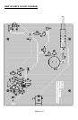
Pay close attention to the Parts Layout Diagram and the silkscreen on the
circuit board for proper orientation (the flat side is a good indicator). Right
next to Q1 is Q2 (another 2SC2498 transistor) so make certain to use the
correct mounting holes.
8. Install Q2, another 2SC2498 transistor (marked C2498 or C2570).
Again note the orientation of the flat side before soldering.
Transistor Q2 provides the amplification needed to keep the 433.42 MHz
RF oscillator going. Q1 and its surrounding parts form a special buffer stage
which isolates the antenna from the oscillator. If it wasn’t for this buffer stage,
the oscillator could stop working whenever things like your fingers or a metal
object are nearby. This pair working together forms a very stable oscillator
which resists a lot of external changes to maintain performance!
9. Install X1, the saw resonator (TO-39 metal case). This is the
component that determines the operating frequency of the oscillator by
interacting with the feedback capacitors surrounding Q2. Note the
silkscreen on the circuit board for proper orientation.