


QAMP-30 • 8
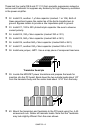
16. Install diode D4, 1N4002 style black epoxy diode. Check positioning
of the banded end.
17. Install jumper JMP2. Use a piece of scrap component lead wire bent
into a "staple" shape and inserted into the board like a component.
Jumpers act as electronic "bridges" carrying signals over PC board circuit
traces underneath.
18. Install C13, .1 µf disc capacitor (marked .1 or 104).
19. Install L4, 10 µH inductor (green body with brown-black-black bands).
20. Install R3, 10 K ohm resistor (brown-black-orange).
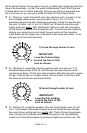
21. Install C2, 10 µf electrolytic capacitor. Electrolytic capacitors are
polarized with a ( + ) and a ( - ) lead and must be installed correctly for
proper operation. Generally, capacitors have their ( - ) lead marked with a
black stripe while PC boards have the ( + ) hole indicated.
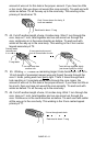
22. Install D1, 6.2 volt Zener diode (gray body with a black band). This
diode provides a stable voltage which is used to provide bias for the
power transistors.
23. Install R5, 1 K ohm resistor (brown-black-red).
24. Install R2, 6.8 K ohm resistor (blue-gray-red).
25. Install R1, 1 K ohm resistor (brown-black-red).
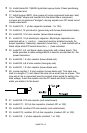
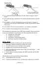
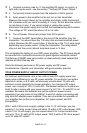
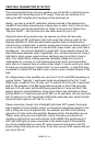
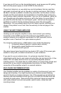
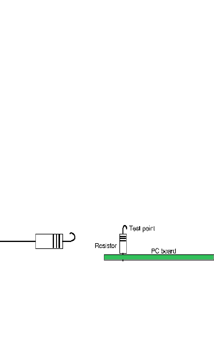
26. Locate another 1 K ohm resistor (brown-black-red). Trim back one
lead to a length of ¼ inch. Bend this wire into a small loop as shown. This
loop will act as a convenient point to connect a test probe for setting the
bias voltage. Insert the resistor into the PC board and hold it carefully
while you solder it to the board.
27. Install R8, 270 ohm resistor (red-violet-brown).
28. Install C11, .001 µf disc capacitor (marked .001 or 102).
29. Install R9, another 270 ohm resistor (red-violet-brown).
30. Install C12, another .001 µf disc capacitor (marked .001 or 102).
31. Install C8, .1 µf disc capacitor (marked .1 or 104).