


FM10A 12
35. Install R10, 10K ohms [brown-black-orange].
The following two capacitors have the identical functions of coupling the RF
output from the collector of Q1 to the RF output jack (J3) and also the
mounting point provided if you wish to use an on-board whip antenna.
36. Install C13, .001 µF (marked .001 or 102 or 1 nf).
37. Install C21, .001 µF (marked .001 or 102 or 1 nf).
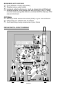
38. The 3 holes for Q1, the 2SC2498 or 2SC2570A RF power amplifier
transistor, should now be quite clear. Press the transistor into place
firmly but gently, so that its body is as close to the board as reasonably
possible. Observe correct placement of the flat side.
39. Install R13, 270 ohms [red-violet-brown].
40. Install C12, .001 µF (marked .001 or 102 or 1 nf).
41. Install C18, .001 µF (marked .001 or 102 or 1 nf).
42. Install C6, .001 µF (marked .001 or 102 or 1 nf).
43. Install C8, 10 pf (marked 10 or 10K).
44. Install C7, 10 pf (marked 10 or 10K).
45. Install Y1, the small silver "can" crystal. Be especially careful when
installing this part as its leads are very small. You may elect to put a
small "dab" of glue on the part to relieve stress and to keep it firmly
attached to the PC board.
46. Install the battery snap connector (without battery); The red wire is
positive and the black wire is negative.
47. Install the battery hold-down clamp, using a scrap component lead
wire looped through the PC board holes and soldered.
48. OPTIONAL: If you purchased the Ramsey case, hardware and whip
antenna set, you may now install the telescopic whip. The antenna is
attached to the PC board at the hole labeled "WHIP" using the small
screw provided.
At this point, all PC board components except C16 have been installed.
Before proceeding, this would be a good time for you or a friend to double-
check your work.