


3
4
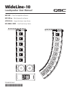
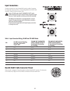
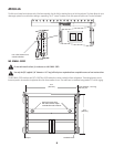
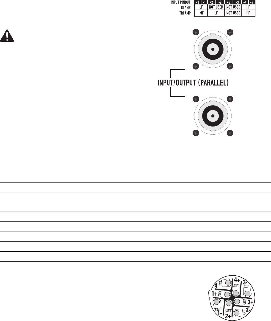
Input Connections
The input connectors are a pair of Neutrik NL8’s wired in parallel. Connections
for bi-amp and tri-amp vary (Table 1). The pin designations for the NL8FC cable
connector is shown for reference, bottom right.
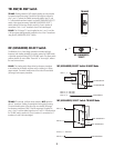
Note! In TRI AMP mode, the MF (UNSHADED) SELECT switch
position determines the input connector wiring! Unexpected results
may occur if switch positions and wiring are not strictly controlled.
The WideLine-10 loudspeaker is not equipped with a crossover
network. All signal processing must be done before connecting
audio power to the loudspeaker.
Do not connect full-range audio to the high-frequency transducer
or damage may result!
PIN
BI AMP Internal Shading
Network Inserted in
Signal Path
TRI AMP MF (UNSHADED)
SELECT Switch Position A
Use External Processing
for Shading,
TRI AMP MF (UNSHADED)
SELECT Switch Position
B Use External Processing
for Shading,
1+ LF + LF A + LF B +
1- LF - LF A - LF B -
2+ Not Used LF B + LF A +
2- Not Used LF B - LF A -
3+ Not Used Not Used Not Used
3- Not Used Not Used Not Used
4+ HF + HF + HF +
4- HF - HF - HF -
Neutrik NL8FC Cable Connector Pinout
Shown, at right, is a diagram of the pin designation inside the Neutrik NL8FC connector. This information
is for reference only. Diagram is of the connector as viewed from the wire-insertion end.
Table 1: Input Connector Wiring, BI AMP and TRI AMP Modes