


5
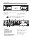
INTRODUCTION- Illustrations
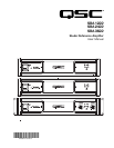
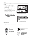
Front Panel (gain control security cover removed)
1- Power switch
2- Channel 1 gain control
3- Power “on” indicator
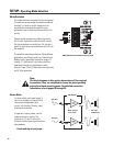
Rear Panel
1- DataPort connector
2- Channel 1 RCA input connector
3- Channel 2 RCA input connector
4- Channel 1 XLR input connector
5- Channel 2 XLR input connector
6- Mode switches
7- XLR connector pinout reference chart
8- Channel 1 Speakon® pinout reference chart
9- Channel 1 Speakon output connector
10- Channel 2 Speakon pinout reference chart
11- Channel 2 Speakon output connector
12- Channel 1 binding post output connectors
13- Channel 2 binding post output connectors
14- Cooling air intake vents
15- Remote trigger in/out jacks
16- Remote Trigger pinout reference chart
17- Serial number decal location
18- Mode switch settings reference chart
19- AC power cord entry (IEC inlet)
4- Channel 1 signal and clip indicators
5- Channel 2 gain control
6- Channel 2 signal and clip indicators
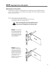
Note! Amplifiers are shipped with the gain controls set at maximum
gain (+29 dB) and with gain control security cover installed. See page
10 for security cover removal and installation information.