


15
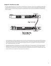
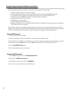
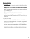
Relay Out
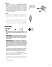
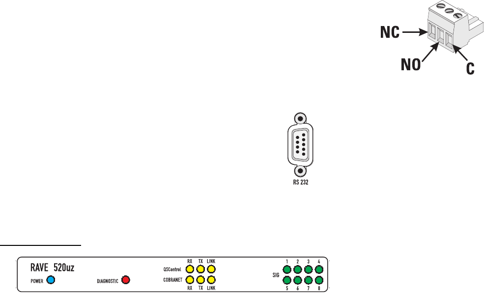
Two sets of relay contacts are provided, RELAY OUT 1 and RELAY
OUT 2. Contacts are floating and rated for 30VDC, 1A. There is one
common terminal, one normally-closed contact terminal and one nor-
mally-open contact terminal. These are labeled as C, NC and NO on
the rear panel. When the relay is not energized, the C terminal is con-
nected to the NC terminal and the NO terminal is not connected;
when the relay is energized the C to NC connection is opened and the
C to NO connection is closed.
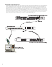
RS-232
The RS-232 is a utility serial port for accessing diagnostic and setup
features. Connect to an available COM port on your PC and communi-
cate using a terminal control program such as Windows Hypertermi-
nal.
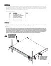
Use a normal serial data cable with a DB-9 male plug to connect to
the RAVE 520uz. To connect the cable, orient the connector properly,
then push into the receptacle until it is firmly seated; tighten the
retaining screws “finger tight”. Communications should be 9600
baud, no parity, 8 data bits, 1 stop bit, and flow control Xon/Xoff.
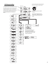
LED Indicators
When the RAVE 520uz is plugged into a properly functioning AC out-
let, it will power up and briefly display a welcome screen on the LCD
display.
POWER Indicator- This blue indicator illuminates when the RAVE
520uz is plugged into a properly functioning AC source. There is no
power switch on the RAVE 520uz. This helps to prevent accidental
system shutdowns.
DIAGNOSTIC Indicator- This red diagnostic LED reports several
possible operational conditions. During boot-up, it is used to continu-
ally blink a “dot-dash” pattern if the power-on memory self-test fails.
During normal operation, if any non-recoverable system fault occurs,
the diagnostic indicator will remain on, requiring a power restart. If
this condition persists, contact QSC’s Technical Services for assis-
tance.
The diagnostic LED is also used to indicate an update is in progress
during a remote firmware update cycle. First, the LED will blink
slowly, indicating the memory erase cycle, then it will blink rapidly,
indicating the memory write cycle. NOTE! During a firmware
update, it is critical the unit remain powered on for the entire
process in order to complete successfully.
The diagnostic LED may also be controlled by using the QSControl.net
software. This feature is particularly helpful for identifying a particu-
lar unit.
(continued, next page)
Relay Out connec-
tions. Refer to text,
at left, for explana-
tion.