6
EN
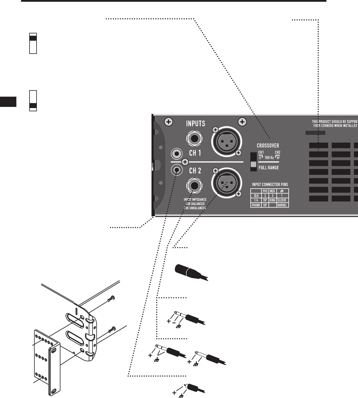
REAR PANEL FEATURES
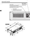
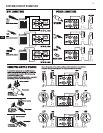
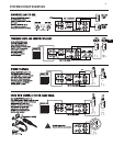
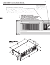
CROSSOVER POSITION
Splits a full-range signal to drive a subwoofer and top box.
CH 1 receives the lows, from 20-100Hz, for the subwoofer.
CH 2 receives 100Hz to 20kHz, to power a full range speaker.
When using CROSSOVER mode, connect signal to CH 1 only.
Use the two Gain controls to balance the LF and HF signals
(see Front Panel).
FULL RANGE POSITION
For normal, 2-channel use with all inputs active.
The crossover is bypassed.
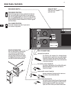
REAR EAR MOUNTING
Rear ears designed for protecting the
rear connector wire dressing and
supporting the amplier in a rack. A
rear rack support mounting kit (model
FG-000031-00 pack of two) is available
from QSC Technical Services Group.
EXHAUST VENT
Keep vent clear. Install in
open-back rack.
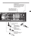
INPUT CONNECTIONS
Pin 2 Positive, Pin 3 Negative, Pin 1 Shield (Ground).
Recommended for long or short runs, either xed or
frequently changed. Each channel’s XLR and TRS
jacks are connected internally, and provide feed thru
to the other connector.
BALANCED 1/4-INCH TRS INPUTS
Tip positive, Ring Negative, Sleeve Shield (Ground).
Recommended for long or short runs that are
frequently changed.
UNBALANCED 1/4-INCH TS INPUTS
Accepts unbalanced 1/4-inch plugs for short runs.
Tip positive, Sleeve Shield (Ground).
UNBALANCED PHONO INPUTS
Tip Positive, Barrel Shield (Ground). Recommended
for semi-permanent connections to nearby sources,
within the same rack. NOTE: when using these
inputs, the TRS or XLR inputs should not be used.
BALANCED XLR INPUTS
CROSSOVER SWITCH


