17
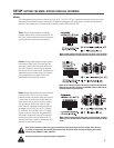
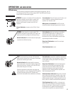
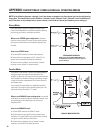
OPERATION: LED INDICATORS
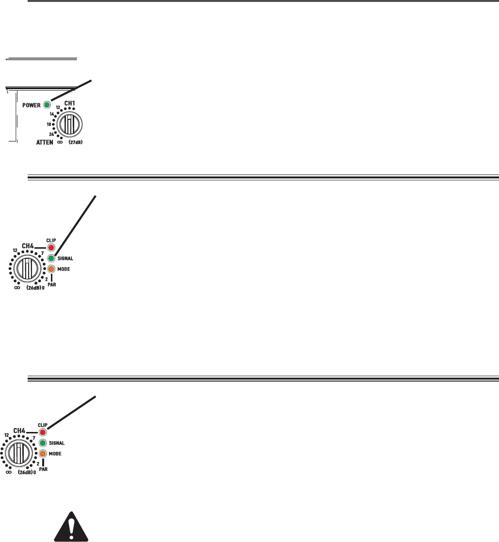
CLIP : Each channel has a red ‘clip’ LED that illumi-
nates when the channel clips. It is located to the upper-
right of each channel’s gain control.
Normal indication:
illuminates briefly at extreme
output power peaks. Occasional clipping at high power
levels may be normal. At power-on, the clip LEDs may
briefly flash during turn-on muting.
Continuous operation at high power may trigger the
thermal protection circuitry, shutting down the amplifier
and fully illuminating the clip LED. Operation will
resume after the amplifier has cooled down sufficiently.
SIGNAL: Each channel has a green ‘signal’ LED
located to the right of its gain control. The ‘signal’ LED
lights up when the input signal is sufficiently strong.
Normal indication:
illuminates when the input signal
is present and sufficiently strong.
POWER: The power ‘on’ indicator LED is located at the
upper-left of the gain control cluster. It is green and
illuminates when the power switch is set to the on
position and AC power is present at the IEC cord
receptacle.
Normal indication:
at power-on the LED will illumi-
nate.
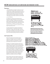
If no indication:
check gain settings, input cables,
connections and audio source. If audio source is
extremely low signal strength, signal LED may not
illuminate; this is normal but indicates that the input
signal strength should be increased.
Occasional illumination:
normal for weak input
signal strength.
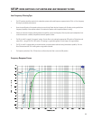
Fully illuminated (on):
normal.
If no indication:
Check AC power cord, AC mains, and
that the DataPort is not being used to force the
amplifier into ‘Standby’ mode.
When power is switched off:
the LED may take
several seconds to extinguish (go out); this is normal.
If no indication:
normal if the amplifier is operated at
nominal output levels. If the input signal is weak, it may
not be capable of driving the amplifier into clipping,
even at full gain.
Occasional illumination:
Occasional clipping (once
briefly every few seconds) when operation at high
power levels does not indicate trouble. Continuous
operation at high power may trigger the thermal
protection circuitry, shutting down the amplifier and
fully illuminating the clip LED.
Illuminated most of the time:
Not normal; for cleaner
sound, reduce the output of the amplifier and/or input
signal to avoid thermal shutdown of the amplifier and
possible speaker damage. If clipping persists at normal
levels, check for shorted or abnormal load impedances.
Fully illuminated (on):
Amplifier is in thermal shut
down. Reduce gain settings or input signal and allow
the amp to cool down. Leave the power on so that the
fan continues to run; operation will automatically
resume after the amplifier has cooled sufficiently.
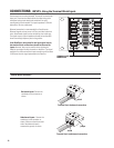
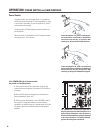
LED Indicators
The LED indicators provide basic operation information to the operator. The ‘nor-
mal’ indications of the LED’s are shown, below. NOTE! The BRDG and PAR mode
indicator LED’s are discussed on page 9.


