3
4
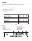
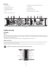
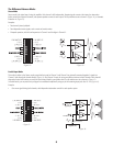
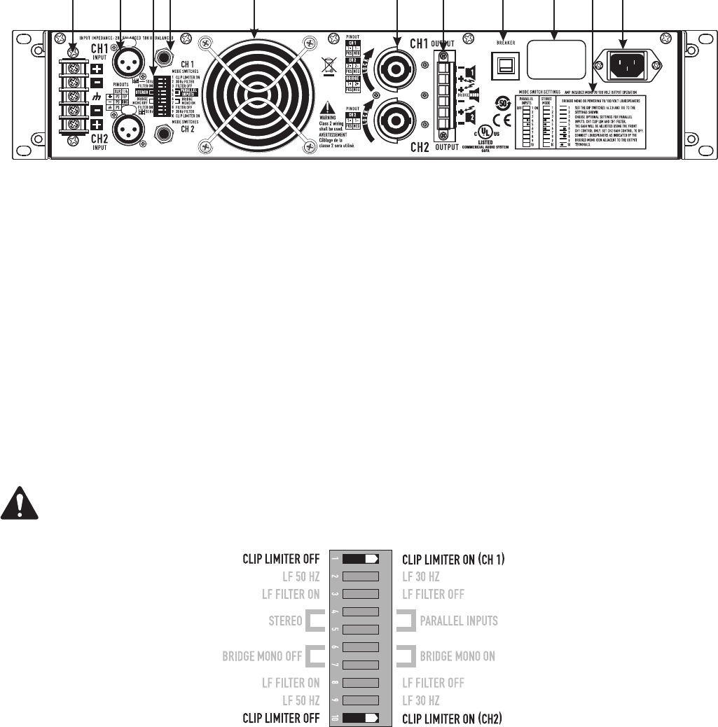
Back Panel
1. Barrier strip input
2. XLR inputs, Channels 1 and 2
3. Configuration dip switches
4. TRS inputs, Channels 1 & 2
5. Fan
6. Speakon™ output, Channel 1 and 2
7. Terminal block connector outputs, Channels 1 and 2
8. Circuit Breaker
9. Serial number label
10. Configuration switch chart
11. IEC power inlet (power cord connector)
Features and setup
Clip Limiter
What it is
When the audio signal drives the amplifier's output circuit beyond its power capability, it clips, flattening the peaks of the waveform. The clip limiter
detects this and reduces the gain to minimize the amount of overdrive. To preserve as much of the program dynamics as possible, limiting reduces the
average program level until peaks barely clip.
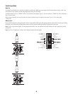
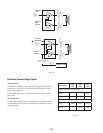
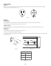
Each channel has its own clip limiter, and you can switch it on or off independently, as shown in (Figure 3).
When to use it (or not)
When driving full-range speakers, clip limiting reduces high-frequency distortion caused by bass overloads. It also protects higher frequency drivers
from excess overdrive and harsh clipping harmonics.
When driving subwoofers, some users let the amplifier clip without limiting because it gives extra “punch” to kick drums and similar sounds.
CAUTION: In bi-amp systems, excessive limiting will affect the frequency balance.
– Figure 3 –
1
2
3 95 6 8 10
114 7
1
2
3
4
5
6
7
9
8
10 11
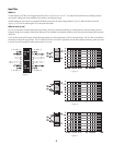
– Figure 2 –


