


L
R
GND
PH LN
Input 2 Input 1
GND
PH LN
Video Out 1
USB 1
L
R
L
R
15V AC
Power
USB 2
Video Out 2
Master
Output
Record
Output
L
R
L
R
GND
PH LN
Input 2 Input 1
GND
PH LN
Video Out 1
USB 1
L
R
L
R
MIC On
MIC Volume High Low
Cue Volume
Phones
0 10Cue 2
Mix
0 10 -dB +dB -dB +dB
Fader Reverse
On
Off
MIC
Cue 1
Pyle Pro Mixer Owner’s Manual – 32 – Pyle Pro Mixer Owner’s Manual
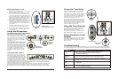
Presetting the Controls Before Use
Since sudden high output levels from your Pyle Pro mixer can damage not only audio devices connected
to the mixer output but your hearing as well (especially if you are using headphones), please adjust
the mixer’s controls BEFORE connecting AC power or turning on the unit.
Set up the mixer controls like this before you start:
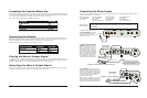
Playing the Mixer’s Output Signal
To record the mixer’s output signal, connect audio patch cords (not supplied) from the mixer’s REC
(Record) L and R jacks to your tape deck’s left and right input jacks.
Power On/Off
Gain
Tone Controls, Treble, Mid and Bass
MIC , CH 1/2 , Master and Cue Levels
Crossfader
OFF
MID
0
0
CENTER
CONTROL SETTING
Connecting the Outputs
After presetting the controls (above), you can then connect the mixer’s output jacks to the output
devices’ input jacks. Before connecting these devices, however, be sure to preset their controls to
avoid any damage to your equipment due to unexpected high output levels.
Set the output devices’ controls like this before you start:
Tape Deck
Amplifier/Receiver
OFF
OFF
FLAT
OUTPUT DEVICE SETTINGCONTROL
POWER
POWER
TONE
To play the mixer’s output signal through your speaker system (for events such as parties, dances,
conferences, etc.) connect an audio patch cord with RCA-type jacks (not supplied) from the mixer’s
MASTER L and R jacks to your receiver/amplifier’s left and right input jacks.
Recording the Mixer’s Output Signal
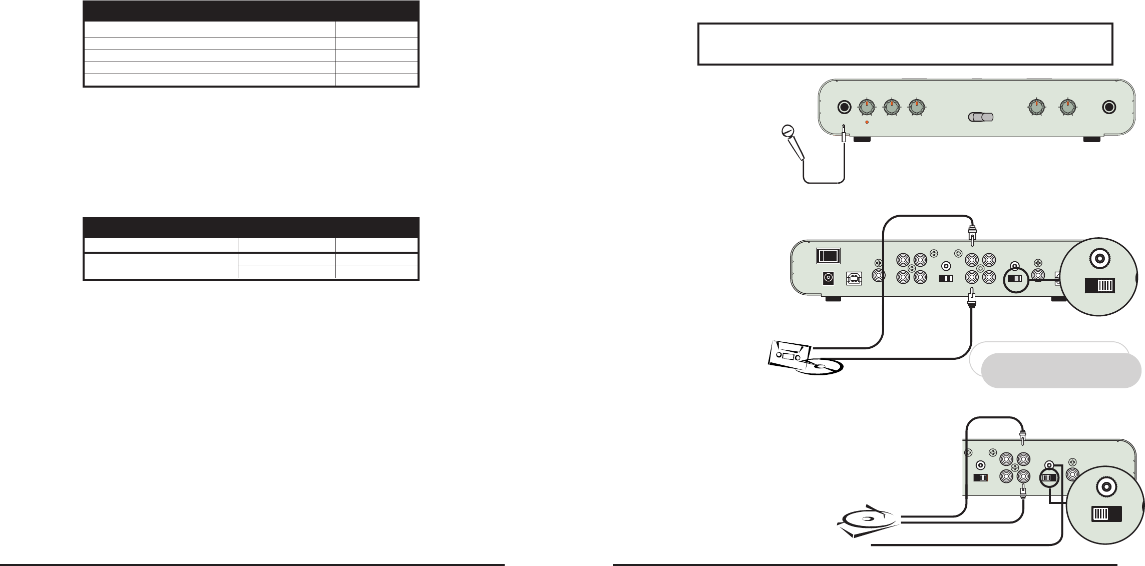
3. Turntables. Connect up to 2
turntables to the input 1 and input
2 jacks. Please note that Phono and
Line use the same jacks. The selector
switch below the jacks should be set
to Phono position if the jacks are
used for phono inputs.
When using a turntable, you should
also securely connect its ground wire
(usually green or black) to the Ground
screw on the input panel of the mixer.
This mixer permits connection of up to five (5) audio input sources, including a microphone. Such a
system might include, for example:
One Microphone
Two Turntables
Two iPods
Please observe
the following:
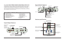
Connect any audio source with a HIGH LEVEL OUTPUT to the input 1 or
input 2 mixer audio input jacks The selector or switch should be set to
LN position.
Connect audio inputs as follows:
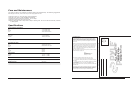
1. DJ Microphone. Connect
the DJ’s Microphone (not
supplied) to the mic input jack.
with a 1/4” plug .
Connecting the Mixer Inputs
One Microphone
One Turntable
Two iPods
One Cassette Deck
One Microphone
One Turntable
One CD player
Two iPods
One Microphone
Two iPods
One CD player
One Rhythm Synth
High Level Output
Audio Source
Use RCA type
patch cables
LEFT output
RIGHT output
CD player, cassette deck, camcorder, VCR, etc.
Be sure to place the input select switch(es)
in positions which reflect what the connected
input source is (Line in or Phono In)!
NOTE!
GND
PH LN
Vid
L
R
2. High Level Output Audio
Sources. Connect 2 sources
(tuner, cassette deck, CD
Player, camcorder or VCR) to
the input jacks for input 1
and input 2. Please note that
Phono and Line use the same
jacks. The selector switch(e)s
below the jacks should be set
to Line position if the jacks
are used for the High Level
input sources described here.
Use RCA type
patch cables
LEFT output
RIGHT output
Magnetic cartridge turntable
GROUND wire from turntable
Use 1/4”
jack
DJ MIC
GND
PH LN
Vid
L
R