


Installation Guidelines
Speaker – Use the largest speaker that can reasonably fit your available
space. For best acoustics the speaker should be sealed to the floor
so that sound going out the front of the speaker is isolated from the
back side.
Volume Switch and Access Jack – Unobtrusive but accessible.
Typically in the floor of tenders and boxcars and on the fuel tanks
of diesels. Many models have removable pieces, doors, etc. where
you can mount these. Volume switch: ¼” hole; Jack: 9/32” hole.
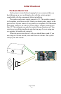
Mounting the Sound Board – Make sure that the sound board will not
touch anything metal. Use the foam tape provided; many modelers
prefer hook and loop tape.
Reed Switches – If you use track magnets and reed switches to trigger
sounds and effects, keep the reed
switches away from the speaker magnet
and strong motor magnets. Reed
switches should ride about ¼’’ above
rail head and be spaced ½’’ on either
side of center. However, it should be
noted that you need the Auxiliary Input
Board, P5T, to connect these reed
switches. Reed Switch: ¼” hole.
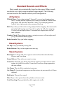
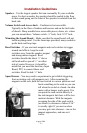
Speed Sensor – You may need to experiment to get reliable triggering
from a rotating axle with magnets on it. After mounting the
magnets on the axle, hold the reed switch in various positions and
hook something to the reed so you can
tell when the switch is closed. An ohm
meter with a beeper works great. You
can point the reed switch directly at
the axle/magnets but there will be less
motion tolerance. With the magnets
sweeping the side of the reed switch
(as shown) a clearance of about 3/16’’
is usually right. If you are too close
you may get extra closures—one as the
magnet approaches, and one as it
leaves.
August 2008
- 13 -