


11
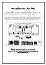
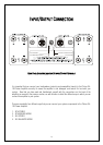
OUTPUT TERMINALS - BRIDGED/MONO
In bridged/mono modes, the loudspeakers utilise only the positive (+) outputs of your Plinius SA-103. In
this configuration power output to the loudspeakers is dramatically increased (around four times as
much), and is commonly used in conjunction with another amplifier for amplification of each channel
from the preamplifier.
Please note that in order to achieve STEREO performance in either of the Mono modes, it will be
necessary to use two Plinius SA-103 Power Amplifiers - one amplifier each for left and right channels.
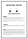
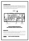
MAINS SWITCH
This heavy-duty rocker switch in the centre of the panel turns the Mains/Line Power to the amplifier ON or
OFF. An LED in the centre of the front panel indicates that the power is on. When first switched on the
power LED will pulse for ten seconds - this is an initialisation sequence, after which the power LED
remains lit. The amplifier draws a moderately high current when switched on. Despite the "Soft Start
Circuit" within the amplifier reducing current demand on the mains as the amplifier is switched on, it is
not good practice to rapidly turn the Mains switch on and off repeatedly.
REMOTE TRIGGER TERMINALS
In order to integrate more effectively into a home theatre system, the Plinius SA-103 has remote trigger
terminals fitted to the rear panel. By connecting a processor with a remote trigger signal to these
terminals, the SA-103 can be put in and out of Class AB/mute by the processor to which it is connected.
When in Class AB/mute the amplifier draws less current and will operate at minimum temperature. The
output relays are also open, disconnecting the loudspeakers. This may be of advantage in a multi-
amplifier and/or remote installations. The Class AB/mute mode can only be activated via the remote
trigger terminals. Polarity of the connections to the remote trigger is not important.
GROUND LIFT SWITCH
This switch is located adjacent to the Mains Input Socket, and allows the signal ground to be
disconnected from the chassis. In some installations a hum loop may exist due to duplicate ground paths
from different equipment. Use this switch to remove the connection from 0V to ground thus allowing
some flexibility in your particular set-up. Note that in both XLR modes the ground lifting switch should
always be set to ‘chassis’.
MAINS POWER CORD IEC CONNECTOR
This connector is where the mains supply cable from your wall connects to the amplifier. You will notice
that a fuse holder is mounted within this connection, and it holds a mains fuse to provide surge and
overload protection for your amplifier.