


17
PREPARATION
PREPARATION
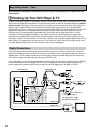
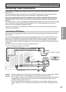
Connecting Your Equipment
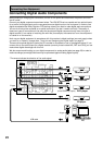
Connecting Video Components
Before making or changing the connections, switch off the power and disconnect the power cord from
the AC outlet.
Connect your video components as shown on this and the following page. For video components (for
example, a DVD player) there are two types of connections to make, video and audio.
Hook up your video signal with either component video, S video or composite video cords (the
quality descends in this order) but you must use the same type of cord as you used to hook up
your TV.
For the audio signal, in order to use digital soundtracks like Dolby Digital or DTS you must hook up a digital
input, with either a coaxial or optical cord (see pages 22 & 23). It is also a good idea to hook up your
components with analog audio connections as well.
If you want to record from your DVD player composite (or S video) cord connections and analog audio
connections are necessary.
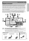
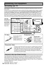
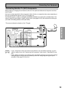
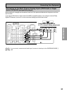
Connecting a DVD player
Before making or changing the connections, switch off the power and disconnect the power cord from
the AC outlet.
Hook up your audio signal with either a coaxial or optical digital cords (you don't need to do both). If you
hook up your DVD/LD player using component video cable connections you might need to setup your
DVD player for component video output as well. See your DVD manual for details. If you have a DVD-
Audio or Super Audio CD (SACD) compatible player, see "Connecting to the Multi Channel Analog Inputs"
on page 21.
You need to hook up your audio with analog connections as well.
memo
• Be sure to make either a digital coaxial or digital optical connection (pictured as DIGITAL
jack 3 or DIGITAL jack 2 in this diagram) but you don't need to make both.
• If your digital connections are different than the default settings you will need to assign
the digital jacks to the proper component(s) with the "Assigning the Digital Inputs"
procedure. See page 91 to do this.
• If your component video connections are different from the default settings, you will
need to assign them with "Assigning the Component Video Inputs". See page 92 to do
this.
(not a PCM-only output)
*The arrows indicate the direction of the signal.
P
C
M
/
2
D
IG
IT
A
L
/
D
T
S
/M
P
E
G
O
U
T
1
O
U
T
2
IN
R
L
(TV/
SAT)
1
IN
1
IN
2
IN
(C
D
-R
/
T
A
P
E
1
)
2
IN
3
(DVD/
LD)
IN
4
(CD)
U
S
B
A
U
D
IO
PLAY
PLAY
C
D
-R
/
T
A
P
E
1
V
C
R
1
/
D
V
R
T
V
/
S
A
T
IN
D
V
D
/
L
D
IN
SUR-
ROUND
BACK
(Single)
(DVD/LD)
(TV/SAT)
FRONT
C
E
N
T
E
R
SUR-
ROUND
S
U
B
W
O
O
F
E
R
PRE OUT
COM
PONENT VIDEO
M
O
N
IT
O
R
O
U
T
Y
P
B
P
R
Y
P
B
P
R
Y
P
B
P
R
V
C
R
2
C
D
P
H
O
N
O
/
L
IN
E
DIGITAL AUDIO AUDIO VIDEO
IN
IN
IN
O
U
T
O
U
T
IN
O
U
T
IN
O
U
T
IN
O
U
T
V
ID
E
O
S
V
ID
E
O
M
D
/
T
A
P
E
2
REC
REC
ASSIGNABLE
MULTI CH IN
RS-232C
MULTI-ROOM
& SOURCE
OUT
IN
MONITOR
OUT
C
O
NT
R
O
L
7
5
Ω
A
N
TEN
N
A
A
M
L
O
O
P
F
M
U
N
B
A
L
R
L
R
L
R
L
L
R
L
R
L
R
MULTI-ROOM
& SOURCE
REMOTE IN
ASSIGNABLE
SUR-
ROUND
BACK
SUR-
ROUND
FRONT
SUB
W
OOF-
ER
CEN-
TER
L
R
L
R
L
R
DVD player
1
23
DIGITAL OUT
C
O
M
P
O
-
N
E
N
T
V
ID
E
O
O
U
T
VIDEO
S-VIDEO
P
B
Y
P
R
AUDIO
L
R
ANALOG
M
O
N
IT
O
R
O
U
T
MULTI-ROOM
& SOURCE
1
2
V
T
R
IG
G
E
R
(D
C
O
U
T
1
2
V
/
1
0
0
m
A
M
A
X
)