


( Connections
)
(~
E~ng~l_is_h
)
(Tn~In_s_t_al_la_t_io_n
~)
(
English)
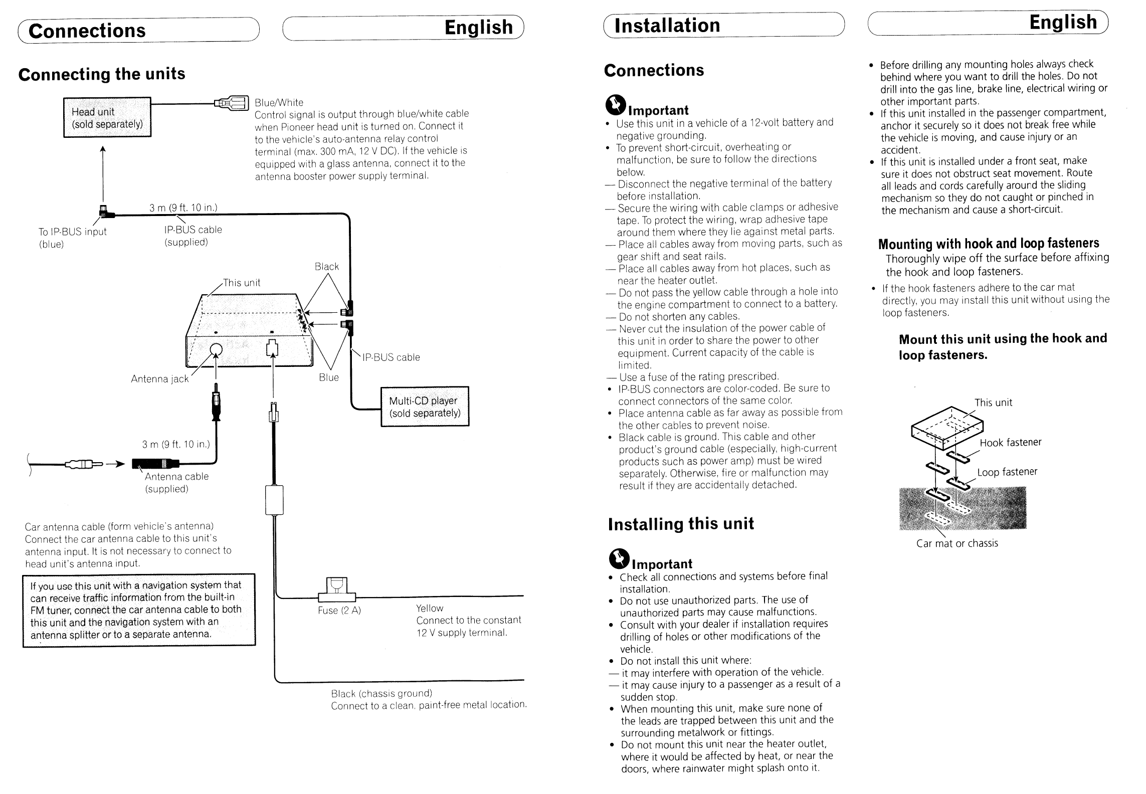
Connecting the units
Mounting
with
hook
and
loop
fasteners
Thoroughly
wipe
off
the
surface before
affixing
the
hook
and
loop
fasteners.
• If the hook fasteners adhere to the car mat
directly, you may install
this
unit
without using the
loop fasteners.
Mount this unit using the hook and
loop fasteners.
Car mat
or
chassis
• Before drilling any mounting holes always check
behind where you
want
to
drill the holes, Do
not
drill into the
gas
line, brake line, electrical wiring
or
other important parts.
• If this unit installed
in
the passenger compartment,
anchor it securely
so
it does
not
break free while
the vehicle
is
moving, and
cause
injury
or
an
accident.
• If this unit
is
installed under a front seat, make
sure
it does
not
obstruct seat movement. Route
all
leads and cords carefully around the sliding
mechanism
so
they do
not
caught or pinched
in
the mechanism and cause a short-circuit.
Installing this unit
Connections
~Important
• Use this unit
in
a vehicle of a 12-volt battery and
negative grounding.
•
To
prevent short-circuit, overheating or
malfunction,
be
sure to follow the directions
below.
- Disconnect the negative
terminal
of the battery
before installation.
- Secure the wiring with cable
clamps
or adhesive
tape.
To
protect the wiring, wrap adhesive tape
arou
nd
them where they lie agai nst metal parts,
- Place all cables away from moving parts, such
as
gear shift and seat rails.
- Place all cables away from hot places, such as
near the heater outlet.
- Do not pass the yellow cable
through
a hole into
the engine
compartment
to
connect
to a battery.
- Do not shorten any cables.
- Never
cut
the insulation of the power cable of
this unit in order to share the power to other
equipment. Current capacity of the cable is
limited,
- Use a fuse of the rati
ng
prescribed.
• IP-BUS connectors are color-coded,
Be
sure to
connect connectors of the same color,
• Place antenna cable
as
far away
as
possible from
the other cables to prevent noise,
• Black cable is ground. This cable and other
product's ground cable (especially, high-current
products such as power amp)
must
be
wired
separately. Otherwise, fire
or
malfunction
may
result if they are accidentally detached.
~Important
• Check
all
connections and systems before final
installation.
•
Do
not
use
unauthorized parts. The
use
of
unauthorized parts may cause malfunctions.
• Consult
with
your dealer
if
installation requires
drilling
of
holes or other modifications
of
the
vehicle.
•
Do
not
install this unit where:
- it may interfere
with
operation
of
the vehicle,
- it may
cause
injury
to
a passenger
as
a result
of
a
sudden stop.
• When mounting this unit, make sure none
of
the leads
are
trapped between this unit and the
surrounding metalwork or fittings.
•
Do
not
mount
this unit near the heater outlet,
where it would be affected by heat, or near the
doors, where rainwater
might
splash
onto
it.
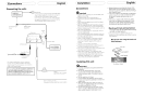
Yellow
Connect to the constant
12
V supply terminal.
Black (chassis ground)
Connect to a clean. paint-free metal location,
Fuse
(2
A)
BluelWhite
Control signal
is
output through blue/white cable
when Pioneer
head
unit
is
turned
on,
Connect
it
to the vehicle's auto-antenna relay control
terminal
(max,
300
mA,
12
V
DC),
If
the vehicle
is
equipped with a glass antenna, connect it to the
antenna booster power supply terminal,
"
IP-BUS
cable
(supplied)
3 m
(9
ft.
10
in.)
Antenna cable
(supplied)
3 m
(9
ft.
10
in.)
. .
A
Antenna
jac~:
-f'"
/
To
Ip·BUS input
(blue)
'H~~d'u'nW"
.....
(sold'$eparately)
r
If you use this
ur')it
with
~rlavigation
system that
can receive traffic information from
thebuilt·in
FM
tuner, cOll.neCtthe car antenna cable to both
this Unit ancLthe'na.vigation system with
an
antenna s'plitfer
orto
a separate antenna.
Car antenna cable (form vehicle's antenna)
Connect the car antenna cable to this unit's
antenna input.
It
is
not necessary to connect to
head
unit's antenna input.