


15
<DRC1129>
En
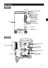
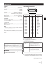
Signal name Pin No. Signal name
GROUND
GROUND
GROUND
GROUND
GROUND
GROUND
GROUND
GROUND
GROUND
GROUND
GROUND
GROUND
NC
GROUND
GROUND
GROUND
GROUND
GROUND
GROUND
GROUND
GROUND
GROUND
GROUND
GROUND
GROUND
26
27
28
29
30
31
32
33
34
35
36
37
38
39
40
41
42
43
44
45
46
47
48
49
50
1
2
3
4
5
6
7
8
9
10
11
12
13
14
15
16
17
18
19
20
21
22
23
24
25
-DB(0)
-DB(1)
-DB(2)
-DB(3)
-DB(4)
-DB(5)
-DB(6)
-DB(7)
-DB(P)
GROUND
GROUND
GROUND
TERMPWR
GROUND
GROUND
-ATN
GROUND
-BSY
-ACK
-RST
-MSG
-SEL
-C/D
-REQ
-I/O
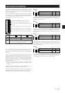
1) Pin layout of SCSI connectors
Notes:
÷
Pin No. 13 is not grounded.
÷
The connectors are of the shielded type.
÷
For details on the control commands, refer to the separate
specifications manual.
SPECIFICATIONS
7 General
System .................................................................. 100 disc changer
Power requirements ..................... AC 100V/120V/230V (switchable)
50/60 Hz
Current drain....................................................................1.6A(100V)
1.4A(120V)
1.0A(230V)
Weight (with disc magazine, without discs) ...... 28.1 kg (61 lb 15 oz)
Dimensions ................................... 263 (W) x 484 (H) x 588 (D) mm
10-11/32 (W) x 19-1/16 (H) x 23-1/8 (D) in
Operating temperature ........................................... +5°C ~ +35°C
*1
+41°F ~ +95°F
*1
Operating humidity .......................... 5% – 85% (no condensation)
*1
Storage temperature .............................................. –40°C ~ +60°C
–40°F ~ +140°F
7 Functions
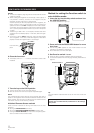
Disc storage (12 cm/5-inch discs) ..................................... 100 discs
Removable disc magazines
.................... 2 magazines which hold 50 discs each can be stored.
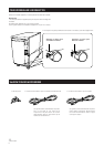
7 Accessories
Door key (for front door locking) ................................................... 2
Power cord .................................................................................... 2
Operating Instructions .................................................................... 1
NOTE:
÷
Specifications and design are subject to possible modifications
without notice, due to improvements.
*1
Because the allowed operating temperature and the allowed operating
humidity are limited by the drive that is installed, be sure to use the
drive under the conditions stipulated in the operating instructions for
the drive.
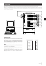
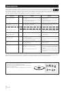
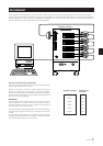
Notes:
÷
Terminate it at both ends of the SCSI bus.
÷
The SCSI interface is single-end type.
÷
Use an SCSI-use high impedance cable (characteristic impedance:
100 ±10
Ω
) with a maximum length of 6 m (total length including
the wiring inside the unit).
The signals driven by SCSI equipment present
the following input characteristics.
True (LOW): VOL = 0.0 to 0.8 V DC
IOL = -0.4 mA to 0.0 mA (0.5 V DC)
False (HIGH): VOH = 2.0 to 5.25 V DC
Input
characteristics
The signals driven by SCSI equipment present
the following output characteristics.
True (LOW): VOL = 0.0 to 0.5 V DC
IOL = 48 mA (0.5 V DC) max.
False (HIGH): VOH = 2.5 to 5.25 V DC
Output
characteristics
2) Electrical specifications of SCSI
SCSI connector specifications
1
¡
±
+
Maintenance
In order to ensure safe and proper functioning of this unit, we
recommend regular maintenance. Extended service life can
be expected if maintained properly.
Published by Pioneer Corporation.
Copyright © 1999 Pioneer Corporation.
All rights reserved.
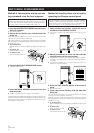
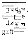
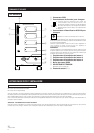
Notes:
÷
For safety, this unit has been designed so that the door cannot
be opened while the built-in reader is operating.
÷
Since the disc rotates at a high speed in the built-in reader,
vibrations or noise may be generated as a result. Note that this
is not a malfunction and that it will not exert adverse effects on
the performance of the unit.