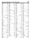
17
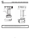
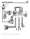
CONNECTING EXTERNAL VIDEO SOURCES
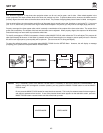
The exact arrangement you use to connect the VCR, camcorder, laserdisc player, and DVD player to your TV set is dependent on the
model and features of each component. Check the owner s manual of each component for the location of video and audio inputs and
outputs.
The following connection diagrams are offered as suggestions. However, you may need to modify them to accommodate your particular
assortment of components and features. For best performance, video and audio cables should be made from coaxial shielded wire.
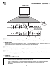
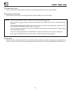
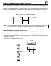
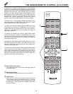
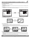
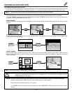
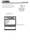
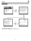
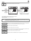
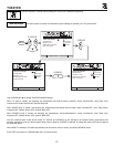
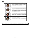
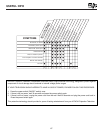
Before Operating External Video Source
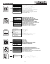
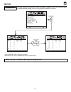
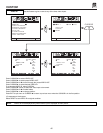
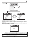
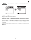
The input mode is changed every time the INPUT button is pressed as shown below. Connect an external source to the INPUT terminal,
then press the INPUT button as necessary to view the input source. (See page 26.)
NOTE: When the TV is set to VIDEO and a video signal is not received from the VIDEO INPUT JACK on the jack panel of the
TV (i.e., VCR/laserdisc player, etc. is not connected or the video device is OFF), the set will appear to be OFF.
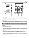
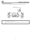
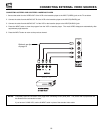
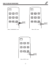
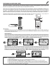
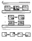
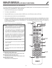
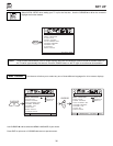
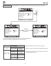
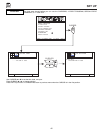
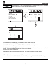
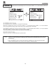
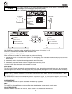
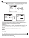
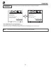
CONNECTING A MONAURAL AUDIO VCR OR LASERDISC PLAYER
1. Connect the cable from the VIDEO OUT of the VCR or the laserdisc player to the INPUT (VIDEO) jack on the TV set below.
2. Connect the cable from the AUDIO OUT of the VCR or the laserdisc player to the INPUT (MONO)/L(AUDIO) jack.
3. Press the INPUT button to view the program from the VCR or the laserdisc player. The VIDEO mode disappears automatically after
approximately eight seconds.
4. Press the INPUT button to return to the previous channel.