


PLM860SAW
7
Rev. 06/03
Ph: 800-421-6511
www.picomacom.com
Installation Procedure
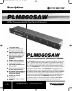
Signal Combining Methods
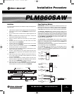
PICO MACOM recommends connecting the headend components in the
following manner: Each of the modulators, signal processors or strip ampli-
fiers output are connected to a combining network. Either a PHC-12G or
a PHC-24G headend combiner may be used to accomplish this purpose.
The PHC-12G or PHC-24G passive headend combiner consists of two
rows of directional couplers combined by a hybrid splitter. Normally, the
odd channels are combined on one row while even channels are combined
on the other row of directional couplers for maximum isolation. The output
of the combiners may be connected to the input of a launch amplifier such
as a CA-30RK550 or CA-30RK1000. The output of the amplifier is con-
nected to the main distribution line.
The CHC16U/550 and CHC16U/860 sixteen channel active combiners
provides both signal combining and post amplification of the headend
signals. Up to 16 channels may be combined using the CHC16U. The
combiner gain is 15 dB per channel.
A 24 channel system hook-up is shown. (The same combining result may
be accomplished by using a single PHC-24G).
The two PHC-12G outputs are combined via a two-way splitter, which is
connected to a CA-30RK1000 launch amplifier. The input levels to the
combiner, whether from a modulator, signal processor or a strip amplifier,
must be at the same amplitude.
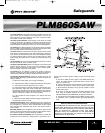
Installation
It is recommended that assistance be available to safely install equipment in
equipment racks.
1. Install chassis in equipment rack (equipment rack sold separately) by
supporting the bottom and rear of PLM860SAW at the desired eleva-
tion in rack.
2. Line up the side holes of chassis with the tapped equipment rack
holes.
3 Insert the provided screws through the side holes in chassis and
thread into the tapped equipment rack holes.
4. Fasten the bottom screws first, then fasten top screws (tighten
securely).
5. Connect a cable from the output of the video source to the video
input connector of the PLM860SAW.
6. Connect a cable from the output of the audio source to the audio
input connector of the PLM860SAW.
7. Connect a cable from the output RF connector of the PLM860SAW
and the input connector of combining system.
8. Connect power cord to receptacle supplying uninterrupted line power
(LED on front panel will illuminate).
9. Connect a cable between the front panel output test point and a
spectrum analyzer or signal level meter. Measure the video and aural
carrier level.
10. Adjust the aural carrier level to 15dB below the level of the video car-
rier by slowly rotating the AURAL LEVEL adjustment on the front
panel of the PLM860SAW.
11. Connect a cable between the combining system test point and a
spectrum analyzer or signal level meter. Measure the video and aural
carrier level of the PLM860SAW and adjacent channels.
12. Adjust the Output level of the PLM860SAW to match the video and
audio carrier levels of adjacent channels by adjusting the OUTPUT
LEVEL adjustment on the front panel of the PLM860SAW.
_
+
_
+
_
+
_
+
+
+
+
+
VIDEO
OUT
COMPOSITE
OUT
70 MHz
IN
OUT
AUDIO OUTPUT LEVEL
VIDEO
LEVEL
RF IN
950-1450
MHz
18V 250mA
LNB POWER
OUT
ON OFF
117V
.35A
60Hz
DAT CLOCK
LANGUAGE
GND
+
_
MONO LEFT RIGHT
AUDIO OUTPUT
FUSE
AC25OV
1/2A
H
V
LRMONO
INV
NOR
AUDIO OUTPUT CONNECTION:
CENTER CONDUCTOR TO MONO+ (POS.)
SHIELD TO MONO- (NEG.)
PLM860SAW MODULATOR
RF OUT
120VAC
AUDIO IN
VIDEO IN
600 VA MAX
'RF OUT' TO TV OR
DISTRIBUTION SYSTEM
+
++
+
+
+
VIDEO IN
AUDIO IN
PR4200IRD SATELLITE RECEIVER
FROM SATELLITE ANTENNA
950 - 1750 MHz
Ch. 2
Ch. 3
Ch. 4
+36dBmV
+60dBmV
SP860
V
A
+55dBmV
+55dBmV
+60dBmV
+10dBmV
+14dBmV
+10dBmV
SP860
XBS
V
A
+52dBmV
+52dBmV
+52dBmV
+10dBmV
+14dBmV
+10dBmV
SP860
V
A
+50dBmV
+50dBmV
+50dBmV
+10dBmV
+14dBmV
+10dBmV
Ch. 2
Ch. 3
Ch. 4
PAD
+65dBmV
EVEN CHANNELS
Ch. 2
Ch. 3
Ch. 4
ODD CHANNELS
+43dBmV
+43dBmV
+39dBmV
+60dBmV
6dB PAD
8dB PAD
RF
IN
RF
IN
RF
IN
RF
IN
RF
IN
RF
IN
PHC-12G
-18dB
CHC-16U/860
+6dB
to
+12dB
CA-30RK1000
CA-30RK1000
ATTENUATOR PAD
ATTENUATOR PAD
ATTENUATOR PAD
XBS
XBS
PLM860SAW
PLM860SAW
PLM860SAW
PLM860SAW Manual.qxd 7/31/03 2:28 PM Page 7