


PLM860SAW
6
Rev. 06/03
Ph: 800-421-6511
www.picomacom.com
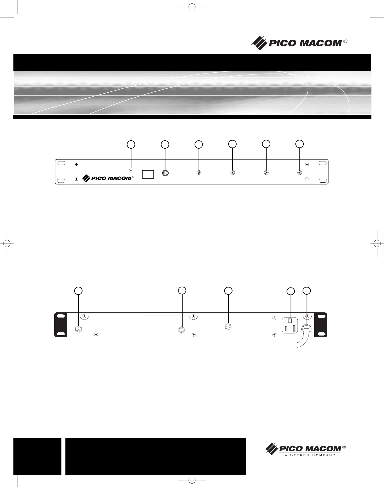
Operation and Controls
POWER
CH-
TEST
POINT
-30dB
RF OUTPUT
LEVEL
AUDIO
MODULATION
AURAL
LEVEL
VIDEO
MODULATION
860MHz Channelized-Agile PLL SAW-Filtered A/V Modulator
PLM860SAW
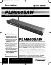
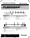
1. Power Indicator:
The LED indicates unit is operating.
2. Test Point:
The -30 dB RF output test point is used to set the RF output level and
monitor channel performance.
3. RF Output Level:
This control sets the RF output level.
4. Audio Modulation:
This control is used to set the audio modulation level.
5. Aural Level:
This potentiometer controls the level of the audio RF carrier.
6. Video Modulation:
This control is used to set the video modulation level.
Front Panel Control
VIDEOIN
AUDIOIN
RFOUT
120VAC
60Hz10W
600WMAX
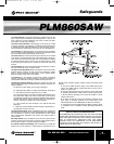
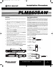
1. Video In:
The baseband video from the satellite receiver or VCR is connected
to this F connector.
2. Audio In:
The baseband audio from the satellite receiver or VCR is connected to
this F connector.
3. RF Out:
The modulated output signal is available on this "F" connector.
4. Convenience Outlet:
Allows looping of power between units.
5. Power Cord:
The three-prong type power plug connects to a 120 VAC, 60 Hz elec-
trical output.
Back Panel Control
1 2 3
4
5 6
1
2
3
4
5
PLM860SAW Manual.qxd 7/31/03 2:28 PM Page 6