


6
CONTACT US TOLL FREE 800-421-6511
www.picomacom.com
PICO MACOM
INSTALLATION
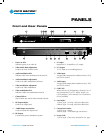
InstaLLatIon
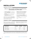
Adherence to these precautions will help prevent problems during
initial installation of the PFAM 550SUB.
Installation Procedures
5. Connect a 1.0 volt peak-to-peak video source to the
“VIDEO IN” on rear panel. Connect the “RF OUT” to a
TV set, and compare the contrast and brightness to a
known signal (use off-air signal to ensure a proper
modulation level). If necessary, adjust the video
modulation until proper contrast is observed.
6. Connect an audio source to the “AUDIO IN” on rear of
the unit. Set audio modulation (peak deviation) to
25 kHz with the audio modulation adjustment. A known
off-air signal and a TV may be used to set adjustment for
equal audio level.
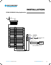
7. Connect the
“RF OUTPUT” to a proper combining
network.
oscillator is factory set to comply with FCC requirements
for frequency accuracy (+/- 5 kHz) in the aeronautical
communication and navigation bands.
1. Connect the I.F. jumper from the I.F. output to the
I.F. input on the rear panel.
2. Connect the
PFAM 550SUB to a 115 VAC ground-
ed receptacle. Observe the lit LED light indicating
power is on.
3. Using a signal level meter or spectrum analyzer,
set the output level.
4. Check the aural carrier level. It should be set at
15 dBmV below the video carrier.
.
WARNING: When connecting the PFAM 550SUB di-
rectly to a TV set, attenuate the output sufficiently to
prevent overdriving the TV. The front panel test point is
useful for monitoring modulator output.
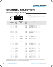
FREQUENCY OFFSETS
T
he Federal Communications Commission requires
that cable system modulators which operate in the
aircraft communications and navigation bands be off-
set in frequency by 12.5 kHz. The PFAM 550SUB PLL
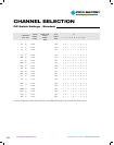
FREQUENCY CHANNEL NUMBER OFFSET
108 to 118 MHz ......................................... A,B,C ................... 14,15,16 ............... 12.5 kHz
118 to 137 MHz ........................................ A-1, A-1 ............... 99,98 .................... 25 kHz
225 to 328.6 MHz ..................................... K - DD ................. 24-40 ....................12.5 kHz
328.6 to 225.4 MHz ................................... FF ......................... 42 ......................... 25 kHz
335.4 to 400 MHz ...................................... GG- QQ................ 43-53 ....................12.5 kHz
Harmonically Related Coherent (HRC) video carriers and Incrementally Related Coherent (IRC) video carriers are
CATV channel assignment methods to reduce the effect of intermodulation products. The technique is used in ex-
pensive phase-locked headends where all units are tied to a master 6.0003 MHz oscillator with a maximum error of
1 Hz.