


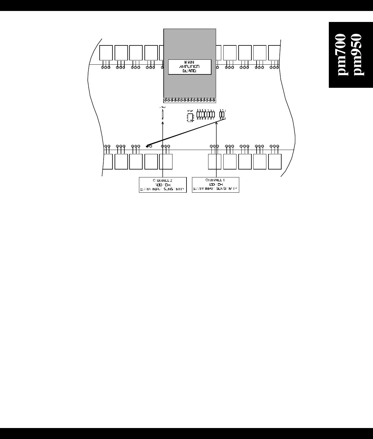
Figure 9
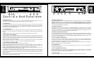
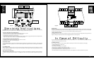
Input Polarity
The XLR input connectors on the pm700 / pm950 are shipped from the factory with pin 2 hot (+), as indicated on the rear panel.
The polarity of the balanced inputs can be reversed by changing four jumpers located on the Input Board. Cross-wire JP3 and JP4
to change the input polarity of CH 1 and cross-wire JP1 and JP2 to change CH2 (see Figure 8).
Clipping Eliminator Defeat
The clipping eliminator circuit can be activated by moving the switch located just inside the input panel to the up position (see
Figure 8). Moving the switch down will return the Clipping Eliminator to normal operation.
In Case of Difficulty
If you’re having trouble or suspect a problem with the pm700/pm950, try some simple troubleshooting before contacting an
Authorized Carver Professional Service Center.
No Sound, No Power
This is usually an indication of a power supply problem, either the power line itself or the amplifier’s power supply.
1. pm700/ pm950 power is switched off.
2. Linecord is disconnected.
3. Poor fit between the plug and AC receptacle.
4. Power off at AC receptacle (check with tester or lamp).
5. The amplifier is plugged into a switched outlet. Verify that the outlet is live.
6. pm700 /pm950 fuse has blown. Check and replace fuse.
7. The thermal breaker in the power transformer has opened. Allow amplifier to cool and the breaker will reset itself.
15
CAUTION ATTENTION
RISQUE DE CHOC ELECTRIQUE
NE PAS OUVRIR
RISK OF ELECTRIC SHOCK
DO NOT OPEN
TO REDUCE THE RISK OF FIRE OR ELECTRIC SHOCK,
DO NOT EXPOSE THIS EQUIPMENT T
O RAIN OR MOISTURE.
WARNING
MADE
IN
USA
RISK OF HAZARDOUS ENERGY! MAKE PROPER
SPEAKER CONNECTIONS. SEE OPERATING
MANUAL BEFORE USING.
WARNING
Serial Number
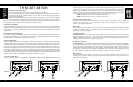
BRIDGE DUAL MODE
NORMAL
JP3
JP4
JP2
JP1
U2 U1
19
20
J1
1
2
STEREO/MONO
SWITCH
CRISS-CROSS
JUMPERS TO CHANGE
INPUT POLARITY
CLIPPING
ELIMINATOR
SWITCH
LEVEL
DEFEAT
SWITCH
ONOFF
ON
OFF
+
–
GND
FOR BRIDGED
OPERATIONS CONSULT
OWNER'S MANUAL
CLIPPING
ELIMINATOR
BEHIND PANEL
ACTIVATED
12
3
+
12
3
PUSH
12
3
PUSH
INPUT IMPEDANCE 25K OHMS EACH LEG TO GROUND (TOTAL 50K OHMS BALANCED)
SEQUENCE
SND RCV
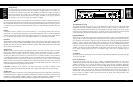
JP5
JP6
JP7
JP8
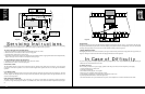
Figure 8
Servicing Instructions
CAUTION: To reduce the risk of electric shock, do not perform any servicing other than that contained in the Operating
Instructions unless you are qualified to do so. Refer all servicing to qualified service personnel.
To remove the input panel and input board:
1. Be sure the amplifier is switched OFF and UNPLUGGED from the AC socket.
2. Remove the two screws located on either side of the input panel.
3. Carefully pull the input board out of the chassis.
4. See Figure 8 for the locations of the Level Defeat Switch, Stereo/Mono Switch, Clipping Eliminator Switch and Input Polarity
jumpers. See Figure 9 for the location of the Input Sensitivity jumpers.
To reinstall the input board and input panel:
5. Carefully insert the input board back into the access hole in the chassis.
6. Reinstall the two screws to secure the input panel.
Stereo/Mono Switch
The Stereo/Mono Switch is located on the input board, which is attached to the input panel (see Figure 8). Leave the switch
centered for normal stereo operation, move it to the left for Bridged Mono operation, and move it to the right for Dual Mono
operation.
Level Defeat Switch
The Level controls can be bypassed by moving the switch located just inside the input panel to the left (see Figure 8). This will
lock the amplifier into full gain (as if the Level pots were fully clockwise). Moving the switch to the right will return the Level
controls to normal operation.
Input Sensitivity Modification
The input sensitivity of the amplifier is set at the factory to 1.5VRMS for rated output. To increase the sensitivity by 6dB to
0.775VRMS, simply install jumpers JP100 (CH 1) and JP200 (CH2), which are located on the Main Amplifier Board (see Figure
9).
14