


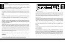

model and enough current to allow full-power operation of all the amplifiers plugged into it. The current
demand of a power amplifier varies depending on several factors, including the impedance of the load, the
output level of the amplifier, and the crest factor and duty cycle of the program material. Under typical
conditions reproducing rock music, with both channels driven into a 4 ohm load to the point where musical
peaks are just at the clipping point, the amplifiers require the following average currents:
pm700: 4.3 amps for 120V versions, 2.2 amps for 230V versions
pm900: 6.0 amps for 120V versions, 3.2 amps for 230V versions
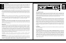
Magnetic Leakage Considerations
The pm700 and pm950 may be mounted without concern for magnetic flux leakage, within the confines of
common sense. For example, it’s not a good idea to mount any power amplifier near a microphone input
transformer or magnetic storage media.
Input Wiring
The 1/4-inch phone jacks and XLR connectors for the input signal can be used with either unbalanced 2-conductor
or balanced 3-conductor cables. Use shielded coaxial cable to conduct the signal from the source (i.e. mixer,
equalizer, CD player) to the amplifier.
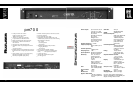
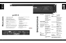
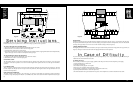
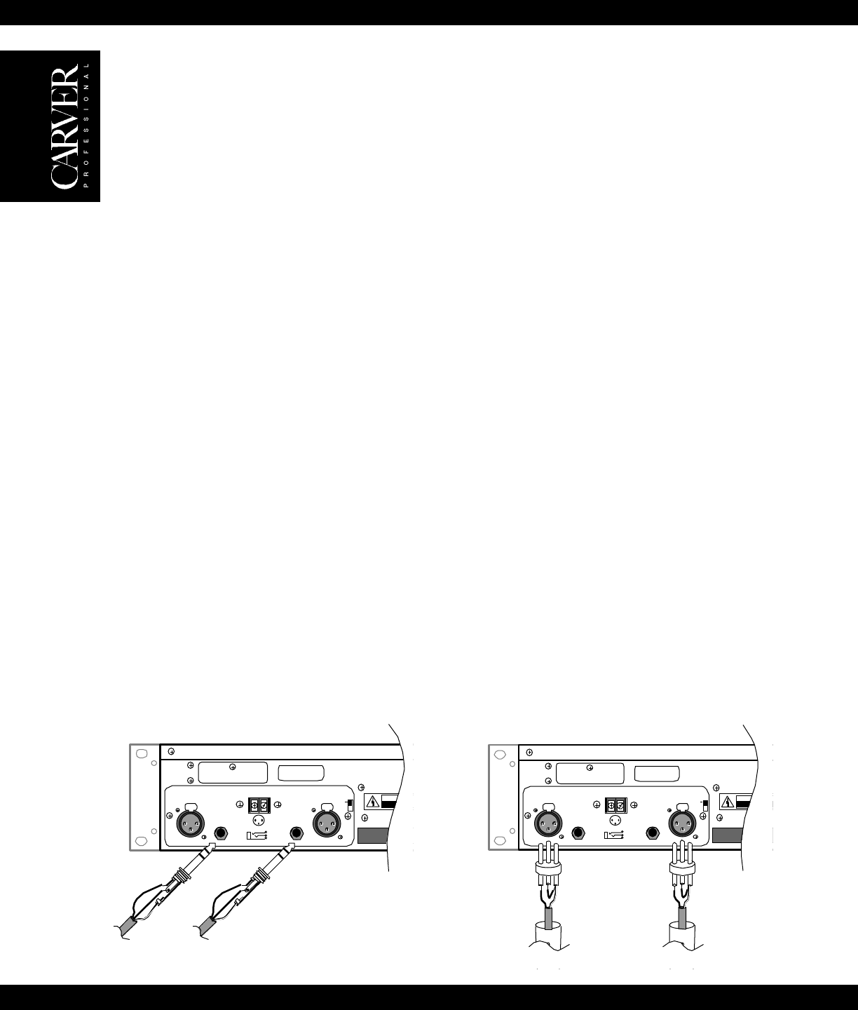
For balanced operation:
1/4-inch phone jack: Use a 3-conductor TRS 1/4” phone plug. The tip of the plug carries the (+, hot, non-inverting)
side of the signal, the ring carries the (–, low, inverting) side of the signal and the sleeve is ground (see Figure 3A).
XLR: Use a male XLR connector. Pin 2 carries the (+, hot, non-inverting) side of the signal, Pin 3 carries the (–, low,
inverting) side of the signal, and Pin 1 is ground (see Figure 3B).
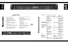
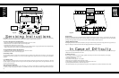
For unbalanced operation:
1/4-inch phone plug: Use a 2-conductor (Tip-Sleeve) 1/4” phone plug. The tip of the plug carries the signal and the
sleeve is ground. The ring connection in the jack is automatically grounded by the sleeve (see Figure 4A). XLR: Pin
2 carries the (+, hot, non-inverting) side of the signal, and Pin 1 is ground. Short Pin 3 to Pin 1 in order to reference
the input differential amplifier for the correct gain (see Figure 4B). Note: For both amplifiers, the gain remains the
same regardless of whether the input is balanced or unbalanced. Note: The polarity of the balanced inputs can be
reversed by changing four jumpers located on the Input Board. See page 14 for more information.
Input Sensitivity
The input sensitivity of the amplifiers are set at the factory to 1.5VR M S for rated output. The input sensitivity can
be changed to 0.775VR M S by adding two jumpers on the Main Amplifier Board. See page 14 of this owner’s
manual for more information.
CAUTION
RISK OF ELECTRIC SHOCK
DO NOT OPEN
TO REDUCE THE RISK OF FIRE OR ELECTRIC SHOCK,
DO NOT EXPOSE THIS EQUIPMENT
W
MADE
IN
USA
RISK OF HAZARDOUS ENERGY! MAKE PROPER
SPEAKER CONNECTIONS. SEE OPERA
MANUAL BEFORE USING.
WARNING
Serial Number
+
–
GND
FOR BRIDGED
OPERATIONS CONSULT
OWNER'S MANUAL
CLIPPING
ELIMINATOR
BEHIND PANEL
ACTIVATED
1
2
3
+
12
3
PUSH
12
3
PUSH
INPUT IMPEDANCE 25K OHMS EACH LEG TO GROUND (TOTAL 50K OHMS BALANCED)
SEQUENCE
SND RCV
–
+
GND
(Shield)
–+ GND
(Shield)
From
Channel 2
From
Channel 1
+
–
GND
FOR BRIDGED
OPERATIONS CONSULT
OWNER'S MANUAL
CLIPPING
ELIMINATOR
BEHIND PANEL
ACTIVATED
1
2
3
+
12
3
PUSH
12
3
PUSH
INPUT IMPEDANCE 25K OHMS EACH LEG TO GROUND (TOTAL 50K OHMS BALANCED)
SEQUENCE
SND RCV
CAUTION
RISK OF ELECTRIC SHOCK
DO NOT OPEN
TO REDUCE THE RISK OF FIRE OR ELECTRIC SHOCK,
DO NOT EXPOSE THIS EQUIPMENT
W
MADE
IN
USA
RISK OF HAZARDOUS ENERGY! MAKE PROPER
SPEAKER CONNECTIONS. SEE OPERA
MANUAL BEFORE USING.
WARNING
Serial Number
TIP
+
SLEEVE
(Shield)
From
Channel 2
From
Channel 1
TIP
+
SLEEVE
(Shield)
Figure 4A Figure 4B
9
CAUTION
RISK OF ELECTRIC SHOCK
DO NOT OPEN
TO REDUCE THE RISK OF FIRE OR ELECTRIC SHOCK,
DO NOT EXPOSE THIS EQUIPMENT
W
MADE
IN
USA
RISK OF HAZARDOUS ENERGY! MAKE PROPER
SPEAKER CONNECTIONS. SEE OPERA
MANUAL BEFORE USING.
WARNING
Serial Number
+
–
GND
FOR BRIDGED
OPERATIONS CONSULT
OWNER'S MANUAL
CLIPPING
ELIMINATOR
BEHIND PANEL
ACTIVATED
1
2
3
+
12
3
PUSH
12
3
PUSH
INPUT IMPEDANCE 25K OHMS EACH LEG TO GROUND (TOTAL 50K OHMS BALANCED)
SEQUENCE
SND RCV
RING
–
TIP
+
SLEEVE
(Shield)
From
Channel 2
RING
–
TIP
+
SLEEVE
(Shield)
From
Channel 1
CAUTION
RISK OF ELECTRIC SHOCK
DO NOT OPEN
TO REDUCE THE RISK OF FIRE OR ELECTRIC SHOCK,
DO NOT EXPOSE THIS EQUIPMENT
WARNING
MADE
IN
USA
RISK OF HAZARDOUS ENERGY! MAKE PROPER
SPEAKER CONNECTIONS. SEE OPERA
MANUAL BEFORE USING.
WARNING
Serial Number
+
–
GND
FOR BRIDGED
OPERATIONS CONSULT
OWNER'S MANUAL
CLIPPING
ELIMINATOR
BEHIND PANEL
ACTIVATED
1
2
3
+
12
3
PUSH
12
3
PUSH
INPUT IMPEDANCE 25K OHMS EACH LEG TO GROUND (TOTAL 50K OHMS BALANCED)
SEQUENCE
SND RCV
+ GND
(Shield)
+ GND
(Shield)
From
Channel 2
From
Channel 1
Figure 3A Figure 3B
Installation
Location and General Precautions
Observe the following precautions when choosing a location for your amplifier.
A. Do not expose the unit to rain or moisture. If a fluid or foreign object should enter the unit, disconnect
the power plug and contact an authorized dealer or service center. Do not pull out the plug by pulling on
the cord; grasp the plug firmly.
B. Protect from heat and allow adequate ventilation. Place away from direct sources of heat, such as heating
vents and radiators. All components produce some heat during operation, so make sure that the ventilation
holes are not covered and that air is allowed to circulate freely behind, beside and above the unit. Excessive heat is
the single greatest source of both short-term and long-term component failure.
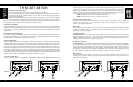
Mechanical Considerations
The pm700 and pm950 require two rack space units (3.5”) and a depth of 13.25” inside the rack, including the rear
supports. Secure the unit mechanically using four screws with washers to prevent marring the front panel. Neoprene
rubber washers are a good choice because they grip the screw head and prevent them from backing out when vibrated
or transported.
Rear Support for Road Applications
If the pm700 or pm950 is rack-mounted and the rack is transported, mechanical support for the rear of the amplifier
is required. This could take the form of a shelf across the rear of the amplifier or brackets that engage the rear of the
unit. This practice is recommended for all electronic instruments.
Thermal Considerations
When the pm700 or pm950 are used free-standing, no thermal considerations are necessary other than keeping the
ventilation holes open. If the amplifiers are rack-mounted, ensure that adequate ventilation exists in front of and
behind the amplifier. When several amplifiers are mounted together in a rack, you may need to provide air inlets from
the outside of the rack. The pm700 and pm950 are fan cooled. The fan is internally mounted so that it draws air in
from the front and exhausts it out the rear. This allows cool air from outside the amplifier to flow over and cool the
power supply components located in front of the heatsinks before being warmed by the heat-producing output
devices, thus providing optimum cooling efficiency. The pm700 and pm950 may be stacked directly on top of each
other without spacer panels. If the amplifiers are used with other amplifiers, ensure that the heat output from the other
amplifiers doesn’t interfere with the ventilation of the pm700 and pm950 (or vice versa).
AC Power Considerations
Ensure that the pm700 or pm950 is plugged into an outlet capable of supplying the correct voltage specified for your
8