


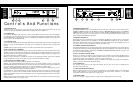
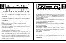


Operating Tips
Using the pm700 / pm950
Once the amplifier has been installed and wired into the system, you are ready to use it. Here are
some tips to help you get the most from it.
• Verify that the switches (Stereo/Mono, Clipping Eliminator and Level Defeat) have been set to the mode
that you want.
• When you power the system up for the first time (out of the carton), it’s a good idea to start with all of
the amplifier level controls turned down, then advance them slowly, one at a time, so that you can confirm
that each amplifier channel is operating normally.
• Be sure that the Input Level controls are set sufficiently high to allow the preceding device to drive the
amplifier to full output. For most installations, this is wide open (fully clockwise).
• Once you have established settings, it is a good idea to mark them down, either on paper, or on pieces of
tape or sticky-dots attached to the amplifier’s panel.
• In bi-amplified (multi-amp) systems, it is a good idea to start with the low-frequency amplifiers turned
off or down, and to check each frequency range from highest to lowest to ensure that each loudspeaker
component is operating correctly.
Accessory Options
The amplifiers have internal connections for installing a variety of accessories to provide additional features
for specific applications. Some of the options available are:
• A precision attenuator which provides attenuation in 0.5dB increments down to -60dB. Settings are made
with a series of DIP switches on the module.
• A programmable two-way electronic crossover that outputs the high frequencies through one channel and
the low frequencies through the other channel.
• High quality balanced input transformers for applications that require electrical isolation.
Contact your local Carver Authorized Dealer for information on these and other accessory modules that
are available for the pm700/ pm950 amplifiers.
13
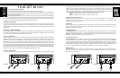
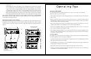
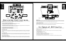
Sequencing ON
Set the MAIN power switch of the amplifiers to off. The amplifiers are now ready to be sequenced
on in one of three ways. 1) The first amplifier may be switched on remotely via an external DC
voltage of +5V to +15V (a common 9V battery will work); 2) The first amplifier may be switched
on manually with its main power switch; 3) The first amplifier has its power switch in the ON
position and all the amplifiers’ AC power is controlled remotely with an AC mains switch. T h e
design of the Sequencing feature insures that the system will continue to operate even if an amplifier
in the sequencing chain should fail or blow a fuse. The control voltage will “carry through” from the
R C V terminal to the SND terminal. Furthermore, once an amplifier has been turned on at the SEQUENCE
R C V terminal, its own power supply will keep the amplifier operating even if the voltage at the RCV t e r m i n a l
is accidentally disconnected or removed.
Remote Turn-On of One or More Amplifiers
The sequencing feature can be used to remotely turn on one amplifier as well as several amplifiers. Leave
the MAIN power switch OFF and connect an external DC voltage as described in step 1 above. A simple
single-pole switch can be used to turn the external DC voltage ON and OFF from a remote location (see
Figure 7).
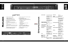
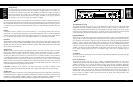
CAUTION
RISK OF ELECTRIC SHOCK
DO NOT OPEN
TO REDUCE THE RISK OF FIRE OR ELECTRIC SHOCK,
DO NOT EXPOSE THIS EQUIPMENT TO RAIN OR MOISTURE.
WARNING
MADE
IN
USA
RISK OF HAZARDOUS ENERGY! MAKE PROPER
SPEAKER CONNECTIONS. SEE OPERATING
MANUAL BEFORE USING.
WARNING
Serial Number
+
–
GND
FOR BRIDGED
OPERATIONS CONSULT
OWNER'S MANUAL
CLIPPING
ELIMINATOR
BEHIND PANEL
ACTIVATED
12
3
+
12
3
PUSH
12
3
PUSH
INPUT IMPEDANCE 25K OHMS EACH LEG TO GROUND (TOTAL 50K OHMS BALANCED)
SEQUENCE
SND RCV
12
3
PUSH
INPUT IMPEDANCE 25K OHMS EACH LEG TO GROUND (TOTAL 50K OHMS BALANCED)
SEQUENCE
SND RCV
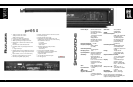
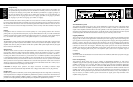
CAUTION
RISK OF ELECTRIC SHOCK
DO NOT OPEN
TO REDUCE THE RISK OF FIRE OR ELECTRIC SHOCK,
DO NOT EXPOSE THIS EQUIPMENT TO RAIN OR MOISTURE.
WARNING
MADE
IN
USA
RISK OF HAZARDOUS ENERGY! MAKE PROPER
SPEAKER CONNECTIONS. SEE OPERATING
MANUAL BEFORE USING.
WARNING
Serial Number
+
–
GND
FOR BRIDGED
OPERATIONS CONSULT
OWNER'S MANUAL
CLIPPING
ELIMINATOR
BEHIND PANEL
ACTIVATED
12
3
+
12
3
PUSH
12
3
PUSH
INPUT IMPEDANCE 25K OHMS EACH LEG TO GROUND (TOTAL 50K OHMS BALANCED)
SEQUENCE
SND RCV
To Next Amplifier
(Ground connections
may be required if the
signal/chassis ground connection is lifted.)
RCV
To Next Amplifier
CAUTION
RISK OF ELECTRIC SHOCK
DO NOT OPEN
TO REDUCE THE RISK OF FIRE OR ELECTRIC SHOCK,
DO NOT EXPOSE THIS EQUIPMENT
WARNING
MADE
IN
USA
RISK OF HAZARDOUS ENERGY! MAKE PROPER
SPEAKER CONNECTIONS. SEE OPERATING
MANUAL BEFORE USING.
WARNING
Serial Number
+
–
GND
FOR BRIDGED
OPERATIONS CONSULT
OWNER'S MANUAL
CLIPPING
ELIMINATOR
BEHIND PANEL
ACTIVATED
12
3
+
12
3
PUSH
12
3
PUSH
INPUT IMPEDANCE 25K OHMS EACH LEG TO GROUND (TOTAL 50K OHMS BALANCED)
SEQUENCE
SND RCV
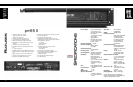
CAUTION
RISK OF ELECTRIC SHOCK
DO NOT OPEN
TO REDUCE THE RISK OF FIRE OR ELECTRIC SHOCK,
DO NOT EXPOSE THIS EQUIPMENT
WARNING
MADE
IN
USA
RISK OF HAZARDOUS ENERGY! MAKE PROPER
SPEAKER CONNECTIONS. SEE OPERATING
MANUAL BEFORE USING.
WARNING
Serial Number
+
–
GND
FOR BRIDGED
OPERATIONS CONSULT
OWNER'S MANUAL
CLIPPING
ELIMINATOR
BEHIND PANEL
ACTIVATED
12
3
+12
3
PUSH
12
3
PUSH
INPUT IMPEDANCE 25K OHMS EACH LEG TO GROUND (TOTAL 50K OHMS BALANCED)
SEQUENCE
SND RCV
These additional ground connections
may be required if the signal/chassis
ground connection is lifted.