


TFA9843AJ_1 © Koninklijke Philips Electronics N.V. 2006. All rights reserved.
Preliminary data sheet Rev. 01 — 28 April 2006 5 of 19
Philips Semiconductors
TFA9843AJ
20 W stereo power amplifier with volume control
8.2.2 Headroom
Typical CD music requires at least 12 dB (factor 15.85) dynamic headroom, compared to
the average power output, for transferring the loudest parts without distortion. At
V
CC
= 18 V and P
o
= 6.5 W (SE with R
L
=4Ω) at THD < 0.5 % (see Figure 5), the
Average Listening Level (ALL) music power without any distortion yields:
(3)
The power dissipation can be derived from Figure 8 (SE) for 0 dB respectively 12 dB
headroom; see Table 4.
For the average listening level a power dissipation of 4.2 W can be used for a heatsink
calculation.
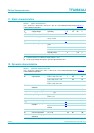
8.3 Mode selection
The TFA9843AJ has four functional modes, which can be selected by applying the proper
DC voltage to pin VC; see Table 5.
8.4 Supply voltage ripple rejection
The supply voltage ripple rejection (SVRR) is measured with an electrolytic capacitor of
150 µF connected to pin SVR with a bandwidth of 20 Hz to 22 kHz. The SVRR as a
function of the frequency is illustrated in Figure 10. A larger capacitor value on pin SVR
improves the ripple rejection behavior at the lower frequencies.
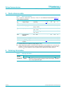
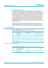
Table 4. Power rating as function of headroom
Headroom Power output (THD < 0.5 %)
(SE)
Power dissipation (P);
both channels driven
0dB P
o
= 6.5 W 8.2 W
12 dB P
o(ALL)
= 410 mW 4.2 W
P
oALLSE,()
6.5
15.85
-------------
410 mW==
Table 5. Mode selection
V
I(VC)
Status Definition
0 V to 0.8 V Standby
in this mode the current consumption is very low
and the outputs are floating; the device is in
Standby mode when V
I(VC)
< 0.8 V
1.2 V to 1.5 V Mute in this mode the amplifier is DC-biased but not
operational (no audio output); this allows the input
coupling capacitors to be charged to avoid plop
noise; the device is in Mute mode when
1.2V<V
I(VC)
< 1.5 V
1.5 V to 5.0 V Volume control in this mode the volume of the amplifier can be
controlled; the gain can be adjusted between the
range of 1.5V<V
I(VC)
< 5.0 V
5.0 V to V
CC
On (maximum gain) in this mode the amplifier has its maximum gain; the
Operating mode is activated at V
I(VC)
> 5.0 V