


TFA9843AJ_1 © Koninklijke Philips Electronics N.V. 2006. All rights reserved.
Preliminary data sheet Rev. 01 — 28 April 2006 4 of 19
Philips Semiconductors
TFA9843AJ
20 W stereo power amplifier with volume control
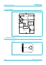
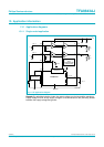
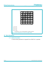
7.2 Pin description
8. Functional description
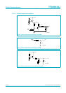
8.1 Input configuration
The input cut-off frequency is as follows:
(1)
Single-ended application: R
i
=60kΩ and C
i
= 220 nF:
(2)
As shown in Equation 2, large capacitor values for the inputs are not necessary; therefore
switch-on delay during charging of the input capacitors can be minimized. This results in a
good low frequency response and good switch-on behavior.
The TFA9843AJ has clamps on the inputs. In Standby mode the voltage on the input pins
is clamped for voltages lower than −0.1 V. When the TFA9843AJ is in Mute, Volume
control or Operating mode (maximum gain) the input clamp voltage is 1 V (RMS).
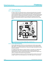
8.2 Power amplifier
The power amplifier is a single-ended amplifier with an all NPN output stage, capable of
delivering a peak output current of 4 A.
8.2.1 Output power measurement
The output power as a function of the supply voltage is measured on the output pins at
THD=10%;seeFigure 7. The maximum output power is limited by the supply voltage of
26 V and the maximum available output current is 4 A repetitive peak current. A minimum
load of 3 Ω is required for supply voltages > 22 V; see Figure 4. The output power is
measured with one channel driven.
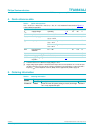
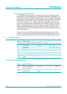
Table 3. Pin description
Symbol Pin Description
IN2 1 input 2
OUT2 2 loudspeaker terminal 2
CIV 3 common input voltage decoupling
IN1 4 input 1
GND 5 ground
SVR 6 half supply voltage decoupling (ripple rejection)
VC 7 volume control input (standby, mute and volume control)
OUT1 8 loudspeaker terminal 1
V
CC
9 supply voltage
f
i3dB–()
1
2π R
i
C
i
×()
-----------------------------
=
f
i3dB–()
1
2π 60 10
3
× 220× 10
9–
×()
-----------------------------------------------------------------
12 Hz==