


April 1985 4
Philips Semiconductors Product specification
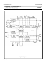
I.F. amplifier and demodulator for
multistandard TV receivers
TDA2549
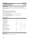
RATINGS
Limiting values in accordance with the Absolute Maximum System (IEC 134)
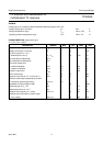
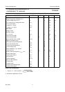
CHARACTERISTICS (measured in fig.5)
V
P
= 12 V; T
amb
=25°C
Supply voltage (pins 13 and 21) V
P
13,8 V
Storage temperature range T
stg
−25 to +125 °C
Operating ambient temperature range T
amb
−25 to +70 °C
PARAMETER SYMBOL MIN. TYP. MAX. UNIT
Supply voltage range V
P
10,8 12 13,2 V
Supply current (pins 13 and 21) I
P
− 82 − mA
I.F. input signal for V
o
=2 V
(between pins 6 and 7) V
i
=V
6-7
− 50 150 µV
Input impedance (differential) |Z
6-7
| − 2 − kΩ
Input capacitance (differential) C
6-7
− 2 − pF
Zero single output level
positive modulation V
22-3
1,6 2 2,3 V
negative modulation V
22-3
3,7 4 4,3 V
Top sync output level V
22-3
1,7 2 2,3 V
Gain control range G
v
50 74 − dB
Signal-to-noise ratio at V
i
= 10 mV (note 1) S/N 50 57 − dB
Maximum video output amplitude for positive
modulation (peak-to-peak value) V
22-3(p-p)
4,5 −−V
Bandwidth of video amplifier (3 dB) B − 5,5 − MHz
Differential gain at V
o
=2V dG − 410%
Differential phase at V
o
=2 V dϕ−210%
Residual carrier signal (r.m.s. value) V
24-3(rms)
− 10 20 mV
Residual second harmonic of carrier signal
(r.m.s. value) V
24-3(rms)
− 20 60 mV