


April 1985 2
Philips Semiconductors Product specification
I.F. amplifier and demodulator for
multistandard TV receivers
TDA2549
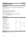
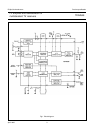
GENERAL DESCRIPTION
The TDA2549 is a complete i.f. circuit with a.f.c., a.g.c., demodulation and video preamplification facilities for
multistandard television receivers. It is capable of handling positively and negatively modulated video signals in both
colour and black/white receivers.
Features
• Gain-controlled wide-band amplifier providing complete i.f. gain
• Synchronous demodulator for positive and negative modulation
• Video preamplifier with noise protection for negative modulation
• Auxiliary video input and output (75 Ω)
• Video switch to select between auxiliary video input signal and demodulated video signal
• A.F.C. circuit with on/off switch and inverter switch
• A.G.C. circuit for positive modulation (mean level) and negative modulation (noise gate)
• A.G.C. output for controlling MOSFET tuners
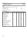
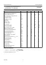
QUICK REFERENCE DATA
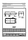
PACKAGE OUTLINE
24-lead DIL; plastic (SOT101A); SOT101-1; 1996 November 19.
Supply voltage (pins 13 and 21) V
P
=V
13;21-3
typ. 12 V
Supply current (pins 13 and 21) I
P
=I
13;21-3
typ. 82 mA
I.F. input signal at V
o
=2 V
(between pins 6 and 7) V
i
=V
6-7
typ. 50 µV
Video output voltage at V
i
=0 V
(between pins 22 and 3)
positive modulation V
o
=V
22-3
typ. 2 V
negative modulation V
o
=V
22-3
typ. 4 V
Gain control range G
v
typ. 74 dB
Signal-to-noise ratio at V
i
= 10 mV S/N typ. 57 dB
A.F.C. output voltage swing (pin 15) V
15-3
min. 10 V
Max. tuner a.g.c. output current
(pin 10) I
10
min. 0,3 mA
Video bandwidth (3 dB) B typ. 5,5 MHz
Auxiliary video input voltage (pin 12)
at V
o
= 2 V (peak-to-peak value) V
12-3(p-p)
typ. 1 V
Auxiliary video output impedance
(pin 14) |Z
14-3
| typ. 7 Ω
Auxiliary video output voltage
(pin 14) V
14-3
typ. 2 V