


April 1991 9
Philips Semiconductors Product specification
IF amplifier/demodulator for FM radio
receivers
TDA1596T
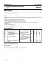
* Connecting pin 13 to ground is only allowed for measuring the current at pin 16. It is not for use in application.
* Without input voltage.
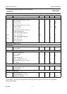
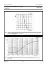
Tuning-stop detector (Figs 10 and 11)
Stop-0: detuning at V
20(rms)
= 10 mV
+∆f for V
15
≥ 3.5 V −−10 kHz
+∆f for V
15
≤ 0.3 V 18 −−kHz
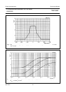
Stop-1: detuning at V
20(rms)
= 10 mV
−∆f for V
14
≥ 3.5 V −−10 kHz
−∆f for V
14
≤ 0.3 V 18 −−kHz
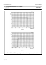
Dependence of STOP-0, STOP-1 on
input voltage (pin 20)
input voltage (RMS value) for
V
20(rms)
V
14
= V
15
≥ 3.5 V 250 −−µV
input voltage (RMS value) for
V
20(rms)
V
14
= V
15
≤ 0.3 V −−50 µV
Output voltage when
V
14, 15
I
14
= I
15
= 1 mA −−0.3 V
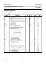
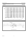
Mode switch and pin 3 (Fig.12)
FM-off position
Control voltage for 60 dB
V
7
muting depth −−1.4 V
FM, mute-on position (pin 3 = output)
Internal bias voltage at
V
7
R
7-17
≥ 10 MΩ−2.8 − V
|I
7
| Input current −−2.5 µA
Output voltage with
V
3
R
3-17
= 10 kΩ; C
3-17
≥ 1 nF* − 2 − V
Output impedance for V
20
= ≤ 5 µV;
R
3-17
I
3
= 500µA −−100 Ω
FM, mute-off position (pin 3 = input)
V
7
Control voltage 0.9 V
5
−−V
I
7
Input current at V
7
= V
5
−−15 µA
R
3-17
Input resistance 1 −−MΩ
Reference voltage source
V
5
Output voltage at I
5
= −1 mA 3.3 3.7 4.1 V
∆V
5
/I
5
Output impedance at I
5
= −1 mA − 40 80 Ω
TC Temperature coefficient − 3.3 − mV/K
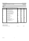
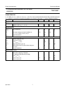
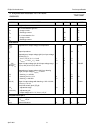
SYMBOL PARAMETER MIN. TYP. MAX. UNIT