


April 1991 6
Philips Semiconductors Product specification
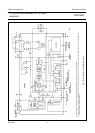
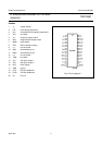
IF amplifier/demodulator for FM radio
receivers
TDA1596T
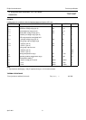
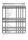
RATINGS
Limiting values in accordance with the Absolute Maximum System (IEC 134)
Note
1. Equivalent to discharging a 100 pF capacitor through a 1.5 kΩ series resistor.
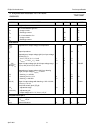
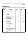
THERMAL RESISTANCE
SYMBOL PARAMETER MIN. MAX. UNIT
V
P
= V
1-17
Supply voltage (pin 1) −0.3 +16 V
V
5-17
Reference voltage range (pin 5) −0.3 + 10 V
V
2-17
Level adjustment range (pin 2) −0.3 + 10 V
V
7-17
Mode switch voltage range (pin 7) −0.3 V
P
V
V
13-17
Control input voltage range (pin 13) −+6V
THD compensation/unweighted field
V
3-17
strength voltage range (pin 3) −0.3 V
P
V
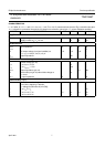
Tuning-stop output voltage range
V
15-17
STOP-0 (pin 15) −0.3 V
P
V
V
14-17
STOP-1 (pin 14) −0.3 V
P
V
Tuning-stop output current
I
15
STOP-0 (pin 15) − 2mA
I
14
STOP-1 (pin 14) − 2mA
T
stg
Storage temperature range −55 + 150 °C
T
amb
Operating ambient temperature range −40 + 85 °C
Electrostatic handling
(1)
V
es
all pins except pins 5 and 6 −2000 + 2000 V
V
es
pin 5 −2000 + 900 V
V
es
pin 6 −2000 + 1600 V
From junction to ambient (in free air) R
th j-a (max.)
= 95 K/W