


April 1991 7
Philips Semiconductors Product specification
IF amplifier/demodulator for FM radio
receivers
TDA1596T
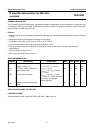
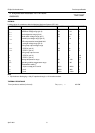
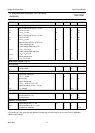
CHARACTERISTICS
f = 10.7 MHz; V
P
= V
1-17
= 8.5 V; V
I
= V
20 (rms)
= 1 mV; T
amb
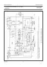
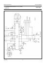
= 25 °C; measured in the circuit of Fig.3; tuned circuit at pins
10, 11 aligned for symmetrical stop pulses; all voltages are referred to ground (pin 17), unless otherwise specified
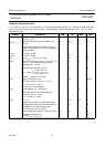
SYMBOL PARAMETER MIN. TYP. MAX. UNIT
Supplies
V
P
= V
1
Supply voltage 7.5 8.5 12.0 V
I
1
Supply current at I
2
= I
7
= 0 mA − 20 26 mA
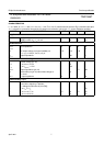
FM demodulator
R
10-11
Input impedance 25 40 55 kΩ
C
10-11
− 6 − pF
V
4
DC output voltage (no-signal condition) at
V
10, 11(p-p)
≤ 100 µV; V
20(rms)
≤ 5 µV
2.75 3.10 3.45 V
R
4-17
Output impedance − 400 −Ω
Mute attenuator control voltage
Control voltage (pin 16)
V
16
at V
20(rms)
≤ 5 µV − 2.0 − V
V
16
at V
20(rms)
= 1 mV − 3.45 − V
R
10-17
Output impedance (pin 16) −−2.0 MΩ
V
2
Level shift input (pin 2) internal bias voltage at
I
2
= 0 mA
− 1.4 − V
R
2-17
input impedance 15 −−kΩ
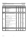
Internal muting (Fig.6)
Internal attenuation of signals
± 22.5 kHz ≤ detuning ≤ ±80 kHz;
A = 20log[∆V
4
(FM mute-off)/∆V
4
(FM)]
A at V
16
≥ 1 V
5
− 0 − dB
A at V
16
= 0.77 V
5
1.5 3.0 4.5 dB
A at V
16
= 0.55 V
5
− 20 − dB