


Philips Semiconductors Product specification
SA5205AWide-band high-frequency amplifier
1997 Nov 07
10
The most important parameter is S
21
. It is defined as the square root
of the power gain, and, in decibels, is equal to voltage gain as
shown below:
Z
D
=Z
IN
=Z
OUT
for the SA5205A
P
IN
)
V
IN
2
Z
D
P
OUT
)
V
OUT
2
Z
D
N
P
OUT
P
IN
+
V
OUT
2
Z
D
V
IN
2
Z
D
+
V
OUT
2
V
IN
2
+ P
I
SA5205
A
Z
D
P
I
=V
I
2
P
I
=Insertion Power Gain
V
I
=Insertion Voltage Gain
Measured value for the
SA5205A = |S
21
|
2
= 100
NP
I
+
P
OUT
P
IN
+ |S
21
|
2
+ 100
and V
I
+
V
OUT
V
IN
+ P
I
Ǹ
+ S
21
+ 10
In decibels:
P
I(dB)
=10 Log | S
21
|
2
= 20dB
V
I(dB)
= 20 Log S
21
= 20dB
∴ P
I(dB)
= V
I(dB)
= S
21(dB)
= 20dB
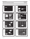
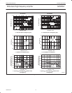
Also measured on the same system are the respective voltage
standing wave ratios. These are shown in Figure 21. The VSWR
can be seen to be below 1.5 across the entire operational frequency
range.
Relationships exist between the input and output return losses and
the voltage standing wave ratios. These relationships are as follows:
INPUT RETURN LOSS=S
11
dB
S
11
dB=20 Log | S
11
|
OUTPUT RETURN LOSS=S
22
dB
S
22
dB=20 Log | S
22
|
INPUT VSWR=≤1.5
OUTPUT VSWR=≤1.5
1dB GAIN COMPRESSION AND SATURATED
OUTPUT POWER
The 1dB gain compression is a measurement of the output power
level where the small-signal insertion gain magnitude decreases
1dB from its low power value. The decrease is due to nonlinearities
in the amplifier, an indication of the point of transition between
small-signal operation and the large signal mode.
The saturated output power is a measure of the amplifier’s ability to
deliver power into an external load. It is the value of the amplifier’s
output power when the input is heavily overdriven. This includes the
sum of the power in all harmonics.
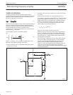
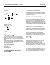
INTERMODULATION INTERCEPT TESTS
The intermodulation intercept is an expression of the low level
linearity of the amplifier. The intermodulation ratio is the difference in
dB between the fundamental output signal level and the generated
distortion product level. The relationship between intercept and
intermodulation ratio is illustrated in Figure 22, which shows product
output levels plotted versus the level of the fundamental output for
two equal strength output signals at different frequencies. The upper
line shows the fundamental output plotted against itself with a 1dB to
1dB slope. The second and third order products lie below the
fundamentals and exhibit a 2:1 and 3:1 slope, respectively.
The intercept point for either product is the intersection of the
extensions of the product curve with the fundamental output.
The intercept point is determined by measuring the intermodulation
ratio at a single output level and projecting along the appropriate
product slope to the point of intersection with the fundamental.
When the intercept point is known, the intermodulation ratio can be
determined by the reverse process. The second order IMR is equal
to the difference between the second order intercept and the
fundamental output level. The third order IMR is equal to twice the
difference between the third order intercept and the fundamental
output level. These are expressed as:
IP
2
=P
OUT
+IMR
2
IP
3
=P
OUT
+IMR
3
/2
where P
OUT
is the power level in dBm of each of a pair of equal
level fundamental output signals, IP
2
and IP
3
are the second and
third order output intercepts in dBm, and IMR
2
and IMR
3
are the
second and third order intermodulation ratios in dB. The
intermodulation intercept is an indicator of intermodulation
performance only in the small signal operating range of the amplifier.
Above some output level which is below the 1dB compression point,
the active device moves into large-signal operation. At this point the
intermodulation products no longer follow the straight line output
slopes, and the intercept description is no longer valid. It is therefore
important to measure IP
2
and IP
3
at output levels well below 1dB
compression. One must be careful, however, not to select too low
levels because the test equipment may not be able to recover the
signal from the noise. For the SA5205A we have chosen an output
level of -10.5dBm with fundamental frequencies of 100.000 and
100.01MHz, respectively.