


4
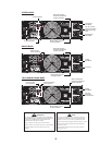
than full clockwise will yield lower system noise at the expense of mixer/system headroom.
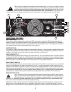
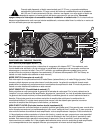
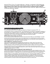
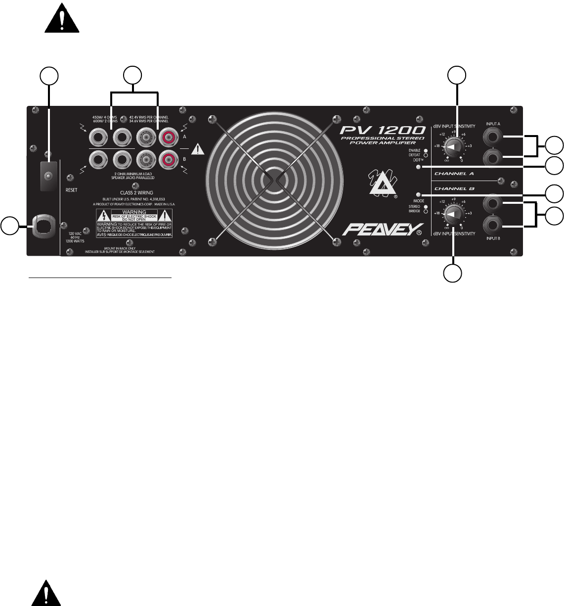
HIGH-Z INPUT JACKS (8)
Two parallel (bridged) input jacks are provided for each channel. This allows for one to be used as a conventional
input, and, simultaneously, the other to be used as a “line out” (Y-cord) to connect to another input jack on this
amplifier or other amps or equipment. These 1/4" jacks are not “chassis grounded” and, when used, will provide a
quasi-balanced input capability due to the unique “ground loop” elimination circuitry associated with each input.
This feature will normally allow “hum-free” operation when relatively short 1/4" cable patches are made between
the jacks on this amp and other jacks on various other equipment that share the same rack with this amp.
SPEAKER OUTPUTS (9)
Two 1/4" jacks and 5-way binding post speaker output terminals are provided for each channel.
Again, for each channel, these outputs are in parallel; hence, the speaker connection cables can
be terminated with 1/4" phone plugs, banana plugs, or stripped wires for use in the binding post
terminals. For sustained high power applications, the use of the binding post terminals is recommended. How-
ever, care must be exercised to assure correct speaker phasing.
Regardless of what connections are used, the typical parallel speaker load should always be limited to 2 ohms
per channel or 4 ohms Bridge mode for any application. Operation at loads of 4 ohms per channel or 8 ohms
Bridge mode is more desirable for sustained operation applications due to the fact that the amplifier will run much
When tripped, the button on the breaker will be outward nearly 1/2" and can be reset by pushing
inward. A normal reset button length is about 1/4". If this “thermal” type breaker does trip, simply
pushing the button back in will reset it, after waiting a brief period of time to allow it to cool down.
REMEMBER, ALWAYS TURN THE POWER OFF BEFORE RESETTING THE BREAKER. If the breaker trips
instantly each time you attempt to reset it, the unit should be taken to a qualified service center for repair.
BACK PANEL FEATURES
DDT
™
SWITCH (5)
This switch is used to either enable or defeat the DDT
™
compressor. Normally the DDT function should be en-
abled to minimize the possibility of either or both channels going into clipping or overload. With DDT defeated, a
severe overload could cause the mains circuit breaker to trip as a matter of course.
(The Peavey DDT compres-
sion system will be covered in greater detail later in this manual.)
MODE SWITCH (6)
This switch is used to select either Stereo or Bridge mode of operation. Care should be exercised whenever the
Bridge mode is selected. Accidental selection of this mode could damage loudspeakers, particularly in biamped
systems.
(The Bridge mode will be covered in greater detail later in this manual
.)
INPUT SENSITIVITY (7)
These controls are used to adjust the input gain of each channel. Thus, they determine how “loud” each channel
of the power amplifier will “play” for a given input signal level. Maximum input gain (minimum sensitivity rating) is
achieved at the full clockwise setting, and this setting yields maximum mixer/system headroom. A setting of less
9
TM
4
7
8
8
10
5
6
7