


8
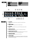
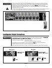
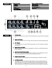
2211.. PPoowweerr AAmmpplliiffiieerr IInnppuutt
Provides a direct input to the power amplifier with an input sensitivity of 1 Volt. When an
RCA phono plug is inserted into this input, the connection between the preamp output and
the power amp input is internally disconnected allowing direct access to the power
amplifier. Using this input along with the preamplifier output (#9), a signal processor can
be inserted between the mixer and the power amplifier.
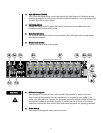
2222.. BBrriiddggee IInn//OOuutt
Provides an output signal that is independent of the Master level, Low EQ, and High EQ
controls. It also may be used as a mixing output point when the similar terminal of another
mixer/amplifier is connected to this terminal. A separate tape recorder output may be
taken from this point without interaction of EQ and Master level control. The input
impedance of the equipment connected to this terminal should be greater than 10k Ohms.
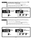
2233.. PPrrooggrraamm IInnppuutt
Provides an auxiliary input that accepts signals from other sources such as another mixer
or mixer/amplifier. The signal level at this input is controlled by the PROGRAM level
control on the front panel and is fed to the mix bus. The Program input may be regarded as
“Channel 9” without PLUG-IN MODULE capability.
NOTE: This input is muted whenever the Mute 1 bus is activated (#24).
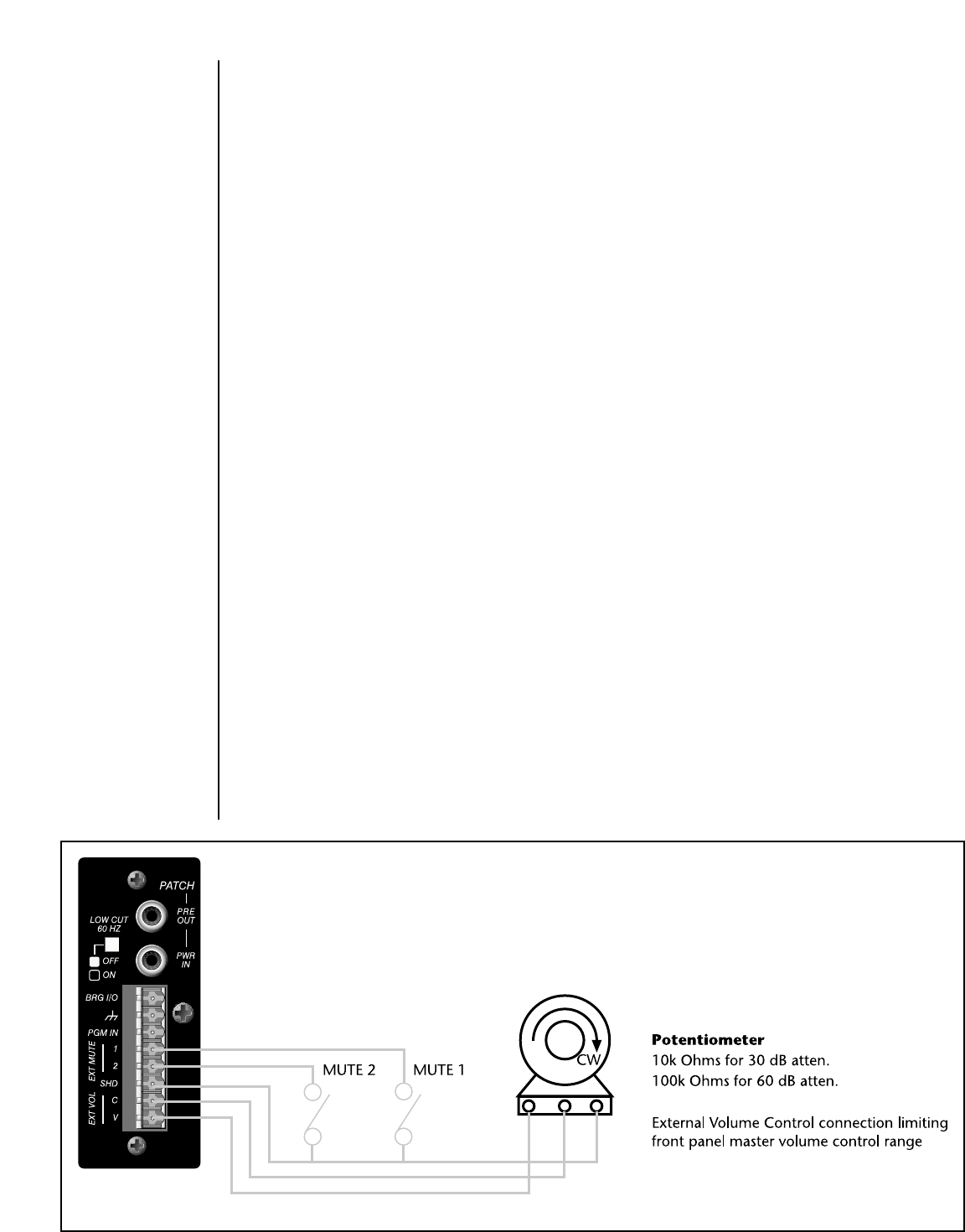
2244.. EExxtt MMuuttee 11//22
When either of these terminals is connected to the Shield terminal (SHD), the respective
mute bus is activated and fed to any PLUG-IN MODULES utilizing its muting function. For
details about the module’s muting function, refer to the individual PLUG-IN MODULE
Instruction Guide.
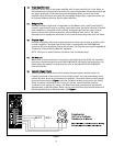
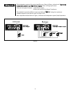
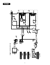
2255.. EExxtteerrnnaall VVoolluummee CCoonnttrrooll
These connections allow the use of an external (remote) master volume control. For
complete command of the volume from the remote control, the front panel Master Level
control (#1) must be set at its maximum (10) position. The remote volume control should
be connected as shown in
FFiigguurree 11
, with the clockwise terminal connected to the Shield
(SHD); the wiper connected to the Control (C); and the counterclockwise terminal
connected to the Voltage (V). Using a 10k Ohm linear taper potentiometer will provide
approximately 30 dB attenuation, while using a 100k Ohm linear taper potentiometer will
provide approximately 60 dB attenuation. See
FFiigguurree 11
.
Figure 1