


amp channel or at the input of the PL-MODULE ELECTRONIC CROSSOVER when
BIAMPING, the (PL-2) transformer must be inserted here. Otherwise a blank plug (PL- 1) is
inserted in this socket.
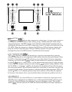
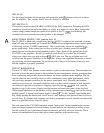
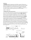
CROSSOVER INPUTS (13)
These are the HIGH-Z INPUTS when an ELECTRONIC CROSSOVER module is installed.
Two parallel input jacks are provided at this point, allowing flexible Y-cord capability. The
output of the LOW-Z XLR input circuitry is always connected to these inputs, which allow the
LOW-Z INPUT to be used as the ELECTRONIC CROSSOVER input if desired. These inputs
can then be used as FULL-RANGE outputs for additional patching capability.
CROSSOVER MODULE RECEPTACLE (14)
This receptacle may only receive a plug-in PL-MODULE ELECTRONIC CROSSOVER.
PL-MODULES are optional accessories and are available in many different crossover frequen-
cies. Some modules contain special equalization and padding for a particular Peavey speaker
enclosure. Always be sure to select the correct module for your speaker system. Other
special-
purpose modules are also available for use with this receptacle. This receptacle supplies both the
input and output patch facilities as well as the power supply “feeds” for these active electronic
devices.
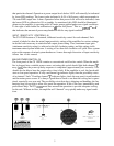
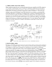
CROSSOVER LOW OUTPUT (15)
This jack supplies the crossed-over low-frequency output from the installed PL-MODULE
ELECTRONIC CROSSOVER. This output must be patched to the appropriate power amp input
jack to “create” an operational biamp system. On some special-purpose modules, this output jack
is not used.
CROSSOVER HIGH OUTPUT (16)
This jack supplies the crossed-over high-frequency output from the installed PL-MODULE
ELECTRONIC CROSSOVER. This output must also be patched to the appropriate power amp
input jack to create an operational biamp system.
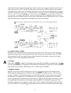
POWER AMPLIFIER INPUT (17)
Two parallel input jacks are provided for each channel, delivering flexible Y-cord capability.
These jacks can be considered the normal power amplifier high-Z input. If a blank plug (PL-1)
is inserted in the crossover accessory socket
(15),
the associated XLR input system is connected
to these input jacks internally, perrnitting the XLR input (11) to be a direct power amplifier input
without the use of a patch cord.
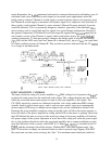
SPEAKER OUTPUTS (18) (19)
Two
l/4”
jacks and 5-way binding post speaker output terminals are provided for each channel,
with all the outputs from each channel in parallel. Thus, the loudspeaker connection cables can
be terminated with
l/4”
phone plugs, banana plugs, or stripped wires for use in the binding post
terminals. For sustained high-power applications, the use of the binding post terminals is highly
recommended; however, care must be exercised to assure correct speaker phasing. Regardless of
what connections are used, the typical parallel speaker load should always be limited to 2 ohms
8