


OPERATION
The
CS
1200X
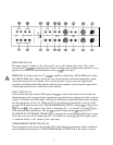
is designed for maximum ease and flexibility of operation. When the unit is
installed and connected as described in the previous sections, operation is as simple as turning on
the mains switch
(S),
turning up the sensitivity controls (4) to the full clockwise setting, and then
adjusting the associated mixer or pre-amplification equipment to supply the necessary signal
levels to provide the desired output level or until the front panel
DDT
active LED indicator
shows that the amplifier is compressin
g.
Further increases in signal levels beyond this point will
not produce any significant increase in output and may cause distortion problems.
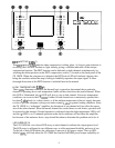
MODES OF OPERATION
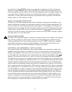
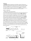
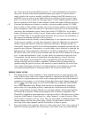
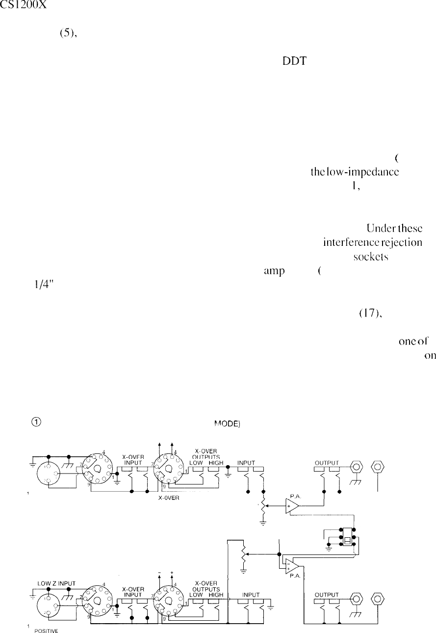
1. STEREO MODE (UNBALANCED INPUTS)
The CS 1200X is shipped from the factory with jumper plugs inserted in the transformer
(
12) and
crossover (14) accessory sockets. These jumper plugs are necessary if
the
low-impedance
con-
nectors (11) are to be used as inputs for each channel. As indicated in Diagram
1,
the XLR
connectors are wired in an unbalanced configuration (pins 1 and 2 are ground: pin 3 is input).
The unbalanced-input configuration is acceptable whenever relatively short cable runs are em-
ployed, or when the associated mixer used has a full transformer-balanced output.
Under
these
circumstances, this configuration will usually provide adequate hum and
interference
rc.jection
for most environments. Notice that the jumper plugs in the crossover accessory
sockets
arc
required to complete the signal patch to the respective power
amp
inputs
(
17). If‘ the normal
unbalanced
l/4”
power amp input jacks are used instead, the jumper plugs are not necessary. It is
suggested, however, that they be left in their respective sockets for possible later usage. As with
all Peavey amplifiers, the CS 1200X has two power amp input jacks per channel
(
17),
which
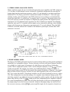
offer considerable flexibility in hook-up possibilities. For monaural operation, the same signal is
applied to both channels; the mixer output is plugged in one of the parallel input jacks in
one
of
the channels, and a short shielded jumper cable is connected between the remaining input jack
on
that channel to one of the parallel input jacks on the other channel. This technique is called
daisy-chaining, and can be repeated many times to patch to additional amplifier channels requir-
ing the same signal feed.
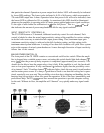
0
PATCH PANEL (STEREO
MODE)
WITH JUMPERS
TRANSFORMER
LOW Z INPUT
CHANNEL
1
2 GROUND
3 POSITIVE
SENSITIVITY
SENSITIVITY
-
TRANSFORMER
CHANNEL
I
2
GROUND
3
POSiTl”E
X-OVER
BRIDGE
STEREO
11