


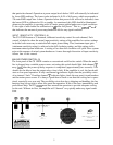
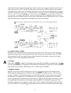
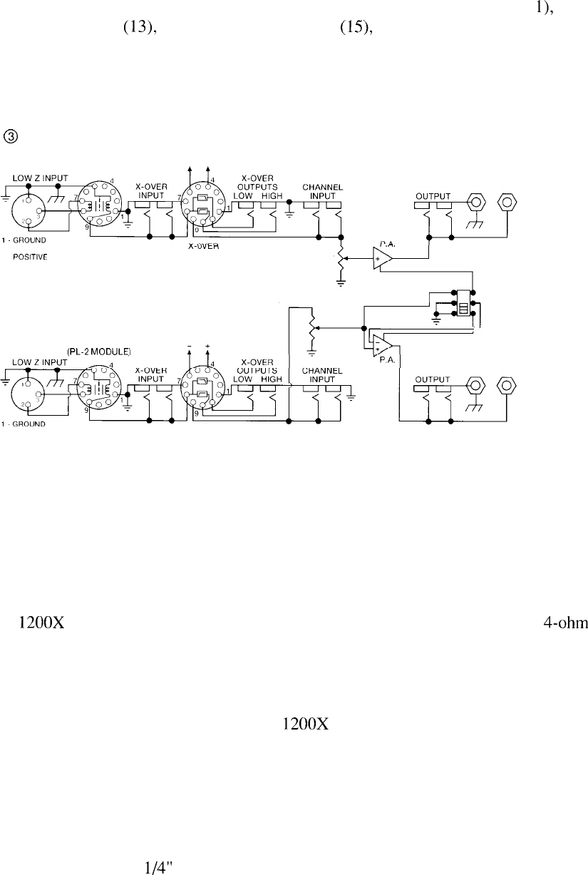
isolated (no longer connected to anything). In other words, the crossover modules and all associ-
ated connectors (as well as the PL-2 transformers and respective XLR connectors) are islands
unto themselves: in this case, two islands with each crossover having a balanced input (1 l), dual
(parallel) unbalanced inputs
(13),
an unbalanced low output
(15),
and an unbalanced high output
(16). In order to complete the system, external patching must be accomplished between the low
and high crossover outputs and the various power amp inputs using shielded patch cords. A patch
diagram showing this arrangement is included at the end of this manual.
@
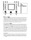
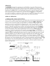
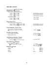
PATCH PANEL (STEREO MODE) WITH CROSSOVER AND INPUT TRANSFORMER MODULES
TRANSFORMER
(PL-2 MODULE)
2 NEGATIVE
3 PcslTl”E
SENSITIVITY
SENSITIVITY
TRANSFORMER
IPL-2 MODULEI
2 NEGATIVE
X-OVER
3 POSITIVE
BRIDGE
STEREO
3A. BIAMP MONO MODE
Obviously, for a monaural biamp system (only one mixer feed), only one crossover module is
required and only one crossover island will be used. In this case, one channel of the CS 1200X
can be patched for the lows and the other channel patched for the highs, resulting in a simple,
compact system with outstanding performance.
A
CAUTION:
Since the CS
1200X
is capable of producing more than 600 watts RMS per channel into a
4-ohm
load, the high-frequency components of the particular loudspeaker system must be able to handle
these power levels reliably. Alternatively, use a smaller power amplifier!
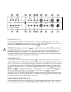
4. BRIDGE MODE
Diagram 4 shows the actual arrangement for the CS
1200X
patch panel in the bridge mode.
Notice that the jumper plugs are inserted in the transformer (12) and crossover (14) accessory
sockets of Island A. These jumper plugs cause the XLR connector of this island to be wired in
the unbalanced configuration (as in Diagram 1) and complete the connection to the Channel A
power amp input jacks (which are now the only active inputs). The Channel A sensitivity control
now determines the sensitivity of the bridge-mode amplifier. The Channel B input jacks and
sensitivity control serve no purpose in this mode, and are actually electronically removed from
the circuit. Both sets of parallel
l/4”
output phone jacks are also not normally used in the bridge
13