


1
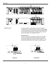
Inputs
Ga
i
n
C
h
4
0dB
x
4
0
0d
B
-6
-
0d
B
-6
-
Inputs
Ga
i
n
C
h
4
0dB
x
4
0
0dB
-6
-
0dB
-6
-
0dB
-6
-
0dB
-6
-
www.crestaudio.com
Crest Audio, Inc.
Fair Lawn, NJ USA
Designed and manufactured in the USA by:
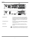
Outputs
Class 2 Wiring
Inputs
Gain
Ch 4
0dB
x40
Gain
Ch 3
0dB
x40
HPF
Gain
Ch 2
0dB
x40
Gain
Ch 1
0dB
x40
HPF
WARNING:
TO REDUCE THE RISK OF FIRE OR ELECTRIC
SHOCK, THIS APPARATUS SHOULD NOT BE EXPOSED TO RAIN OR
MOISTURE AND OBJECTS FILLED WITH LIQUIDS, SUCH AS VASES,
SHOULD NOT BE PLACED ON THIS APPARATUS.
AVIS:
DANS LE BUT DE REDUIRE LES RISQUES D’INCENDIE OU
DE DECHARGE ELECTRIQUE, CET APPREIL NE DOIT PAS ETRE
EXPOSE A LA PLUIE OU A L’HUMIDITE ET AUCUN OBJET REMPLI
DE LIQUIDE, TEL QU’UN VASE, NE DOIT ETRE POSE SUR CELUI-CI.
AVIS:
RISQUE DE CHOC ÉLECTRIQUE-NE PAS OUVRIR
CAUTION
RISK OF ELECTRIC SHOCK
DO NOT OPEN
MOUNT IN RACK ONLY.
INSTALLER SUR SUPPORT DE MONTAGE SEULEMENT.
220 Watts @ 70.7 V
220 Watts @ 8 Ohms
160 Watts @ 4 Ohms
Output Power per Channel
+
Ch
1
+
Ch
2
+
Ch
3
+
Ch
4
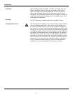
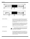
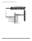
The inputs are balanced, three-pin Phoenix connectors. Connect the
incoming signals to the respective positive (+), negative (-) and ground ( )
terminals as indicated on the unit. Channel input sensitivity is 0dBu (0.775V)
when the 0dB gain setting is selected. This equates to a gain of 90.3x. Gain
can also be decreased to x40 with the gain setting switch (see # 12 Gain
Select). If using bridged, see the Bridged Mode section.
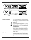
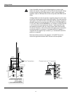
The Phoenix connectors are wired as: Pin 1 is positive; Pin 2 is negative;
and Pin 3 is chassis ground. Normally balanced inputs are wired using
two-conductor shielded cable as shown in the following diagram. For un-
balanced (single-ended) inputs‚ the single conductor is wired to Pin 1 and
the shield is connected to Pins 2 & 3 as shown in the following diagram.
Balanced Unbalanced