


7 8 9
10
11
12
3
51
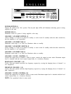
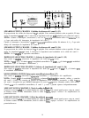
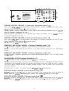
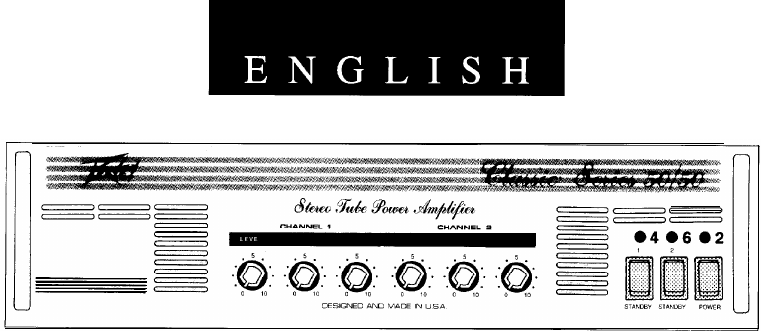
POWER SWITCH (1)
Depress the switch to the “On” position. The red pilot light (LED) will illuminate indicating power is being
supplied to the unit.
POWER LED (2)
Illuminates when AC power is being supplied to the amp.
CHANNEL 1 STANDBY SWITCH (3)
Allows channel 1 of amp to be placed in standby or active mode. In standby mode the tubes remain hot,
but the amplifier is not operational.
CHANNEL 1 STANDBY LED (4)
Illuminates when amp is on. Does not illuminate when on standby.
CHANNEL 2 STANDYBY SWITCH (5)
Allows channel 2 of amp to be placed in standby or active mode. In standby mode the tubes remain hot,
but the amplifier is not operational.
CHANNEL 2 STANDBY LED (6)
Illuminates when amp is on. Does not illuminate when on standby.
CHANNEL 1 LEVEL CONTROL (7)
Controls the output level of channel 1 when in stereo; controls the output in mono mode. Maximum output
level is obtained with the level control rotated fully in a clockwise direction.
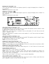
RESONANCE CHANNEL 1 (8)
Used to fine tune speaker enclosure low frequency response by varying the damping factor of channel 1 at
low frequencies.
PRESENCE CHANNEL 1 (9)
Used to fine tune speaker enclosure high frequency response by varying the damping factor of channel 1 at
high frequencies.
CHANNEL 2 LEVEL CONTROL (10)
Controls the output level of channel 2 when in stereo mode. Maximum output level is obtained with the level
control rotated fully in a clockwise direction.
NOTE: Not operational when in mono mode.