


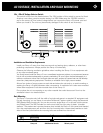
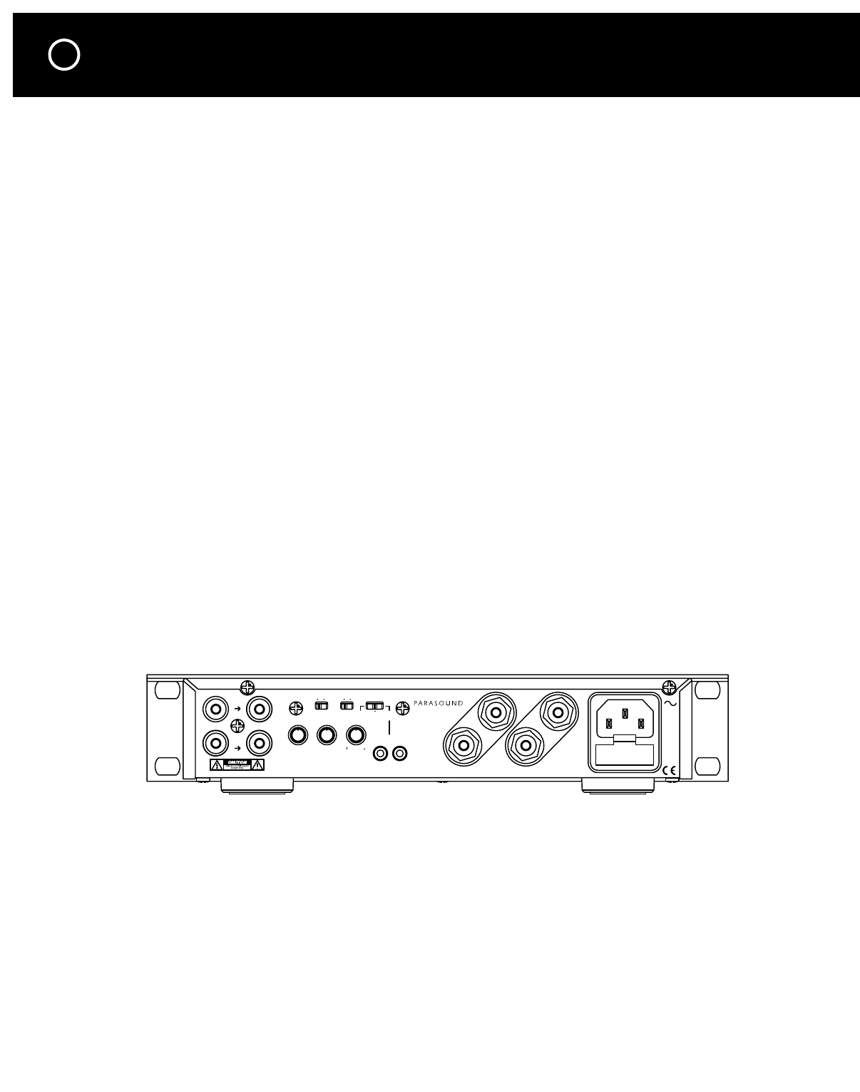
REAR PANEL CONNECTIONS AND CONTROLS
4
Connection Precautions
Disconnect the AC cord before making or changing any input, trigger, or speaker wire connections.
Make sure there is no strain or tension on any wires that could cause them to pull loose.
Audio In Jacks
Connect the cables from your preamplifier or multi-room controller’s output jacks to the Zamp
v.3 L and R audio In jacks.
Loop Jacks
The L and R Loop jacks are convenient output connections for an additional power amplifier.
These jacks eliminate the need for “Y” connectors to drive both your Zamp v.3 and another
amplifier from the same source.
R and L Level Knobs
You can adjust the gain for each channel to achieve the lowest noise and widest dynamic range
in your system or installation. Start with the 12 o’clock mid-position of each knob on the Zamp
v.3 and turn each one clockwise for higher gain or counter-clockwise for lower gain.
Note: We encourage you to experiment with different gain settings for your preamp or con-
troller and the Zamp v.3 to find those gain settings where your system’s background noise is
lowest. Among sound professionals this procedure is known as “gain staging.”
Speaker Connections
Each pair of five-way speaker terminals accepts bare speaker wires up to AWG 12, wires termi-
nated with
1
⁄4" spade lugs, and single or dual banana plugs which are
3
⁄4" (19mm) apart.
If you use bare wires, remove only enough insulation, about
1
⁄2" (12mm) for each exposed bare
wire to insert through the small hole in the side of the binding post. Before inserting a bare
wire, twist the strands tightly between your fingers to prevent strays that might touch the chas-
sis or another terminal and cause a short circuit. If you have soldering experience you may want
to “tin” the stripped bare wire with solder for a cleaner termination and to prevent the wire
from oxidizing.
Correct Speaker Polarity is Important
As you connect the speaker wires, you can see that the insulation on one of the two wires in
each pair has either printing or a raised ridge. The marking lets you know which wire you con-
nected to the positive speaker terminal at its other end.
Make sure the + wire you attach to each Zamp v.3 + speaker terminal is attached to the +
terminal of the speaker for that channel.
Stereo - Mono Switch
The Zamp v.3 power should always be turned off before moving this switch.
For normal operation this switch must be to the right in its ST (stereo) position.
For bridged mono operation, move this switch left to its Mono position.
Note: Stereo sound will be faint and very distorted if you accidentally leave this switch in its
Mono position.
AC Voltage Selector On Bottom
In Out
Zamp V.3 Zone Amplifier
Parasound Products, Inc.
San Francisco, CA USA
L-
L+
R-
R+
R
L
In
Zamp v.3
AVIS: RISQUE DE CHOC ELECTRIQUE-NE PAS OUVRIR.
11 5 V
/230V
60Hz
/50Hz
5W
3A
Fuse
Only
Auto On
ManAudio
Sens
Use
R
In
12V
LevelRL
Gnd Lift
Loop
Loop
Mono St