


PARASOUND JC 1 DESIGN OVERVIEW
15
Designed by John Curl and CTC Builders
Parasound has worked with legendary designer John
Curl since 1989. John has been a legend among
audiophiles and electronic engineers since the mid
‘70s. He pioneered measurements to correlate musical
accuracy with the materials used in component parts,
worked with world-class touring companies, and has
designed highly coveted audio classics. These designs
include the original Mark Levinson JC-2, Denneson
JC-80, Vendetta Phono Preamplier, master recorders
for Wilson Audio and Mobile Fidelity; and the mixing
consoles used in live concerts by The Grateful Dead
and at the Montreux Jazz Festival in Switzerland.
In 2000 John formed CTC Builders to develop totally
uncompromised analog products. CTC’s products have
earned the utmost respect from the most discerning
audiophiles and high end magazine reviewers.
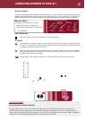
The Power Supply
The heart of the power supply is a 10 Ampere
(continuous!) toroid transformer, chosen for its
efciency, low hum eld, and high power rating.
Encapsulating this massive power transformer in an
epoxy-lled steel canister assures ultra-quiet
performance.
To create the high voltage B+ and B- supply rails for
the output stage, we use high-speed, fast-recovery
rectier diodes and four enormous 33,000 uF Nichicon
"Gold Tune" series electrolytic lter capacitors, chosen
for their low Equivalent Series Resistance (ESR) and
dielectric absorption. In addition, these lter capacitors
are bypassed with smaller polypropylene capacitors
to reduce AC ripple in the DC supply and to further
eliminate noise and interference that is generated in
AC power lines from computers and other appliances
in the home.
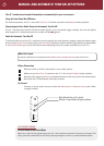
Relay-Bypassed Soft Start Circuit
When the JC 1 is rst turned on, there is a signicant
amount of in-rush current to required to charge up
the enormous power supply capacitors. In order to
suppress this in-rush current and keep nuisance
tripping of circuit breakers, we employ NTC (negative
temperature coefcient) resistors. These resistors cut
the in-rush current by about 50%. Once they heat up,
they essentially become a jumper with zero ohms
resistance. However, the JC 1 goes one step further
for this circuit. After the NTC resistors have done their
job of suppressing in-rush current a gold contact relay
automatically is activated to jump across the NTC
resistors to completely bypass them. This extra step
insures that the resistors do not restrict any current
whatsoever to the power supply once the JC 1 is in full
operation.
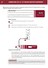
Complementary Configuration
Each stage of amplication has transistors fed by
the positive DC power supply and complementary
transistors fed by the negative DC power supply.
Thus, half of the devices amplify the positive half
of the musical waveform while the other half of the
devices amplify the negative half. This complementary
topology is inherently linear, and reduces distortion
and improves sonic accuracy.
The Input Stage
The JC 1’s input stage uses matched pairs of discrete
JFETs arranged in a differential conguration. JFETs
are ideal for the input stage because their inherently
high impedance is unaffected by the impedance of
source components. Differential conguration provides
superior noise reduction. These precision input JFETs
are also cascoded to produce the current necessary to
drive the MOSFET drivers in the following stage.
The Driver Stage
The driver stage provides critical amplication for which
we employ complementary matched pairs of MOSFETs
selected for their tube-like sonic qualities. MOSFETs
tend to generate less odd-order harmonic distortion
than bipolar transistors. This is important because
odd-order distortion sounds unnatural and fatiguing
to the human ear, whereas even-order distortion is
less offensive because it is consonant, rather than
dissonant. Our MOSFET driver stage prevents the
harshness and brittle sound so often found in other
ampliers.
The B+ and B- power for our input and driver stage
cannot sag under load because it is supplied by
independent transformer secondary windings with
independent rectication, ltering, and voltage
regulation. This preserves soundstage width and depth
even when the JC 1 output stage is drawing enormous
current.
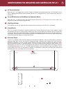
The Output Stage
The amplier’s sonic characteristics are established by
its input and driver stages. Now, the sole job of its
output stage is to deliver the enormous current and
voltage from its power supply to the speakers. Bipolar
output transistors are better than MOSFETS in the
output stage because of their higher safe operating
area (SOA) and inherent ruggedness. The JC 1’s output
stage employs nine pairs of high current (15-ampere)
bipolar transistors to insure long-term reliability, even
with continuous high power operation and challenging
speaker loads. Lightning-fast (60 MHz) transistors
respond instantly to complex demands in the musical
signal, virtually eliminating distortions that occur with
slower transistors. Slew rate limiting and Transient
Intermodulation Distortion (TIM) are simply not an
issue in the JC 1.