


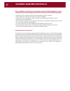
YOU SHOULD KNOW
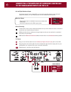
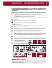
Balanced XLR Jacks and Their Pin Configuration
The balanced inputs of the A 23 use XLR jacks that conform to the industry standard of: Pin
1: Ground, Pin 2: Positive (+), Pin 3: Negative (--). The balanced outputs on some components
use terminals with 3 screws instead of XLR jacks. These are compatible with the A 23 as long
as you match the bare wires to the corresponding pins on the XLR plug: + to pin 2, - to pin 3,
and Ground to pin 1.
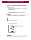
Interconnect Cables and Their Color Codes
Common color codes for input and output jacks are red for right and white for left. Match the
colors at the outputs from your preamplifier or surround controller to the inputs on your A 23
so you’ll always hear the channels in their intended position.
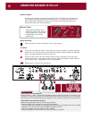
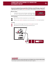
Left and Right Balanced Input Jacks
Balanced connections will give you the best sound. If your preamplifier or surround controller
has balanced XLR output jacks, we recommend that you connect them to these inputs. Refer
to the Balanced and Unbalanced Lines in the Technically Speaking section for additional
information about why we recommend using balanced lines.
What You’ll Need:
• One pair of balanced interconnect cables with XLR connectors
• A preamplifier or surround controller with
balanced connectors.
Before Connecting
Leave the A 23’s AC cord disconnected until you have made all other connections to
prevent any surprise burst of sound.
Make sure that all your cables are long enough so they are not strained or stretched
once they are connected.
Make sure the Balanced - Unbalanced switch on the rear of the A 23 is in its Balanced
(up) position.
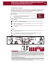
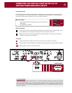
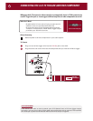
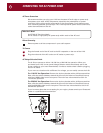
To Connect
Plug the male end of the balanced interconnect cable into the Balanced Right Channel
input jack on the A 23.
Plug the female end of the cable into the balanced right channel output jack on
your preamplifier (or a channel from your surround controller).
Repeat steps 1 and 2 above to connect the left channel.
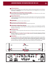
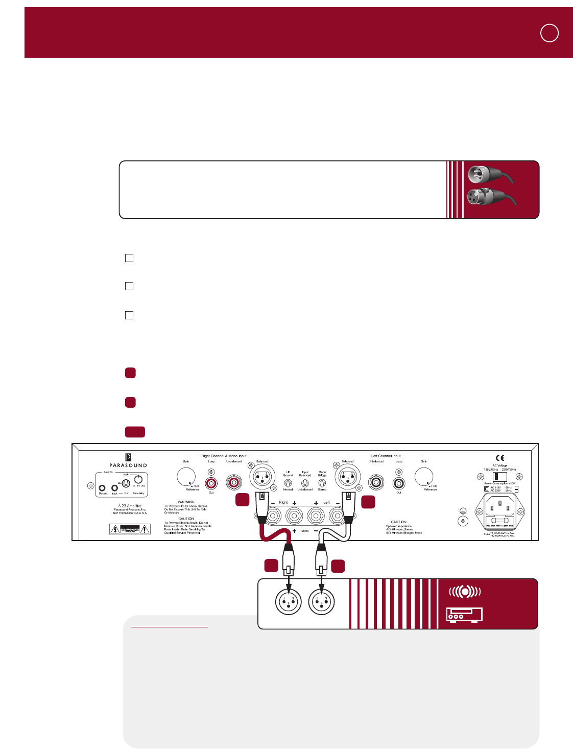
CONNECTING A PREAMPLIFIER OR SURROUND CONTROLLER
TO THE BALANCED INPUTS ON THE A 23
1
2
3&4
2
XLR Connectors
Male
Female
3
1
CAUTION
2
4
Right
Left
COMPONENTS
SURROUND
SOUND
CONTROLLER
PREAMP
OUTPUTS
or