


CONCEPTSYSTEM EXAMPLESCONNECTIONSPRODUCTSBLOCK DIAGRAMS
31
3
CONNECTIONS
WA-BA240N
CONCEPT SYSTEM EXAMPLES CONNECTIONS PRODUCTS BLOCK DIAGRAMS
30
3
CONNECTIONS
WA-BA240N
Important
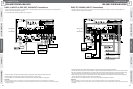
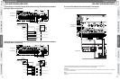
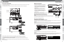
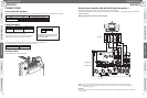
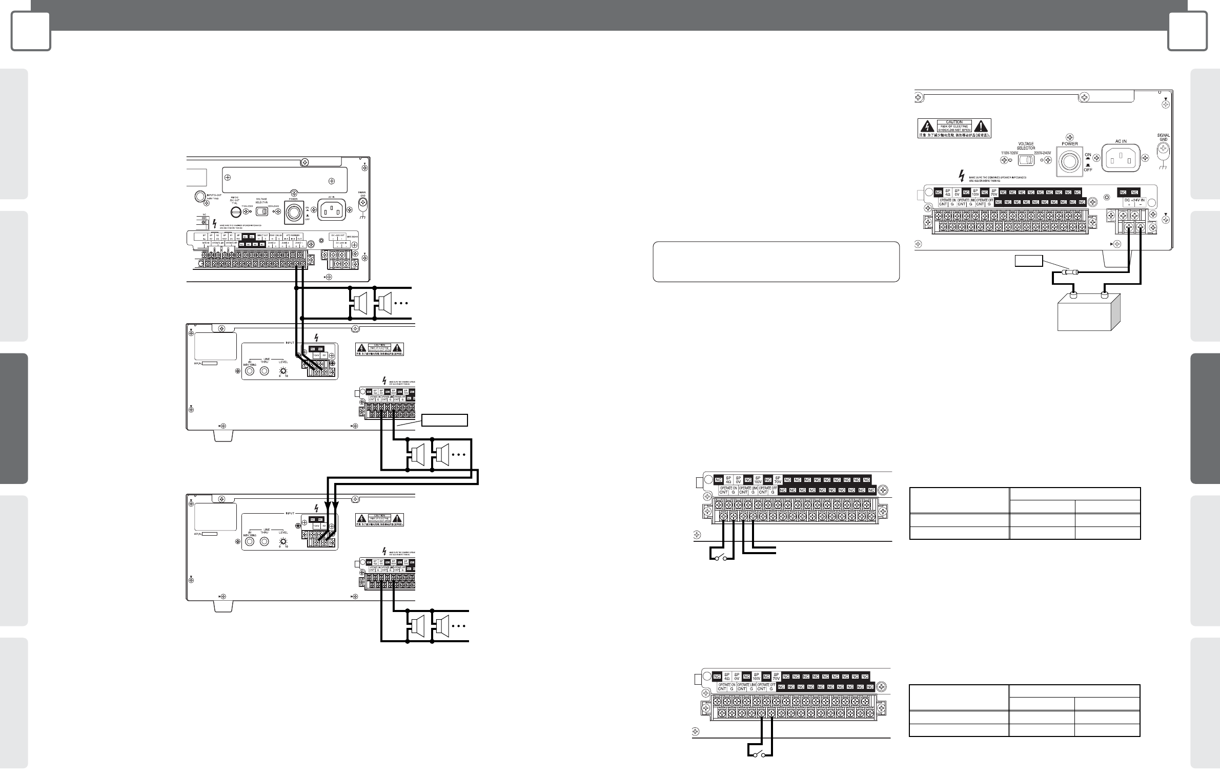
100 V Input Connection
• Connecting power amplifier output for high-impedance loudspeakers as shown below makes it possible to expand the number
of speakers through the Amplifier.
• The following illustration is a connection example with the Mixing Power Amplifier (WA-MA120N or WA-MA240N).
• ZONE 2, ZONE 3 or DIRECT OUT terminals are also available for output of WA-MA120N or WA-MA240N.
• To perform operation link control, interconnect the OPERATE ON/LINK/OFF terminals of the various devices.
For information about operation on/off control, see page 31.
• Use amplifiers that support high-impedance loudspeakers when using amplifiers except WA-MA120N or WA-MA240N.
Important:
When the rated output of the power amplifier connected to the Amplifier's 100 V terminal is less than 100 V, the output of the Amplifier will be
lower than the rated output.
WA-MA120N
or
WA-MA240N
WA-BA240N
WA-BA240N
Caution
DC+24V
+–
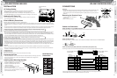
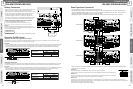
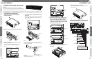
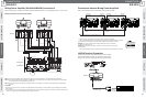
Battery Connection
• Make sure the external battery is a 24 V Lead Acid
battery (or two 12 V batteries in series connection).
Panasonic Corporation holds no responsibility for any
Amplifier fault operation or other inconveniences
resulting from using any other batteries except that
indicated above.
• Use the formula below to determine the battery
capacity that is necessary to support the amount of
operating time required. Note, however, that the
actual amount of operation time provided by a battery
varies greatly in accordance with the Amplifier's
signal output level.
Battery Capacity [AH] = Amplifier Normal DC
Consumption Current [A]* x Required Operating Time [H]
* Based on IEC60065 standards. Refer to SPECIFICATIONS (page 53).
Caution:
Be sure to turn off power (AC) before installing or removing a battery. To protect the battery, provide
a 30 A fuse between the battery + terminal and the Amplifier's + terminal. Take care to ensure proper
battery polarity and to avoid shorts while working.
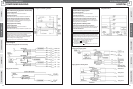
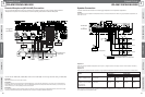
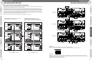
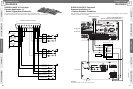
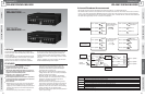
Operation On/Off Control
• Operation On Control and Operation Link Control
The Amplifier can be put into the operation mode externally by no-voltage make contact. The Amplifier can also cause other
linked equipment to enter operation mode when it enters the operation mode.
Important:
In order for external operation control to be performed, the POWER switch on the back of the Amplifier must be on, and the OPERATE switch
on the front must be OFF so the Amplifier is in the non-operation (standby) mode. The Amplifier's current operation/non-operation mode is
determined by the relationship between external control (no-voltage make contact) status and the Amplifier's OPERATE switch setting.
• Operation Off Control
The Amplifier can be put into the non-operation (standby) mode externally by no-voltage make contact.
Important:
In order for operation off control to be performed, the POWER switch on the back of the Amplifier must be on, and the OPERATE switch on the
front must be ON so the Amplifier is in the operation mode. The Amplifier's current operation/non-operation mode is determined by the
relationship between external control (no-voltage make contract) status and the Amplifier's OPERATE switch setting.
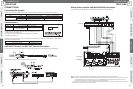
No-voltage make contact
Make
Amplifier's OPERATE
switch position
Other device power on link
No-voltage make contact
Break
Operation Mode
Non-operation Mode
Operation Mode
Not Depressed (OFF)
Depressed (ON)
Operation Mode
No-voltage make contact
No-voltage make contact
Make
Amplifier's OPERATE
switch position
Break
Non-operation Mode Non-operation Mode
Non-operation Mode
Not Depressed (OFF)
Depressed (ON)
Operation Mode